Facebook
 Google
 GitHub
 Linkedin
I am planning to purchase a TV lift stand that can be operated by wireless or wired remote control. I want to automate the lift so that it goes up when the TV is turned on and down when the TV is turned off. Unlike some models, there is no 12 V trigger port on the lift. But the supplier suggests that the wired remote can be hacked/replaced with some circuitry to accomplish the automation.
What is needed: When the TV is turned on, a momentary (a few ms?) contact closure needs to be created between the remote's COM and UP pins. Then when the TV is turned off, a momentary contact closure needs to be created between the remote's COM and DOWN pins.
My idea: Use either the TV's USB output voltage as a trigger, or a smart power bar (like Smart Power Bar on Amazon) (where the TV's load turns the other outlets on the bar on/off) with a basic transformer as the trigger. Then I need to build a device/circuit that will translate the trigger's leading edge into one momentary closure and the the trailing edge into a different momentary closure.
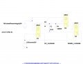
This seems similar to some other discussions I have seen on the forum (for example this one), but I got the idea from this relay diagram that this task can be accomplished using just relays and basic components.
I sketched a circuit in LTspice, using the DPDT relay models from the hardware design forum. When I run the simulator, the output seems to give what I want (when the TV-linked power source turns on there is a momentary connection of the U1 (UP) relay, and when that power source turns off there is a momentary connection of the U3 (DOWN) relay).
My questions:
1. Is this circuit actually a reasonable/safe solution?
2. Are there any changes improvements that would be appropriate (or necessary for safety)?
3. How can I actually go about building it? This is my first attempt at electronic circuit building since Physics labs 20+ years ago. Where can I source parts (I live in Canada - is mouser.ca or leeselectronic.com likely to have what I need)? What actual parts should be used for the relays/diode (I assume capacitors/resistors are easy enough)? What should I use to hold the parts together (I have basic soldering skills/equipment)? What kind of enclosure should I use to safely contain the project?
Thank you for any advice/assistance.
(This is also my first thread post, so I also welcome any suggestions regarding the presentation of my questions.)
What is needed: When the TV is turned on, a momentary (a few ms?) contact closure needs to be created between the remote's COM and UP pins. Then when the TV is turned off, a momentary contact closure needs to be created between the remote's COM and DOWN pins.
My idea: Use either the TV's USB output voltage as a trigger, or a smart power bar (like Smart Power Bar on Amazon) (where the TV's load turns the other outlets on the bar on/off) with a basic transformer as the trigger. Then I need to build a device/circuit that will translate the trigger's leading edge into one momentary closure and the the trailing edge into a different momentary closure.
This seems similar to some other discussions I have seen on the forum (for example this one), but I got the idea from this relay diagram that this task can be accomplished using just relays and basic components.
I sketched a circuit in LTspice, using the DPDT relay models from the hardware design forum. When I run the simulator, the output seems to give what I want (when the TV-linked power source turns on there is a momentary connection of the U1 (UP) relay, and when that power source turns off there is a momentary connection of the U3 (DOWN) relay).
My questions:
1. Is this circuit actually a reasonable/safe solution?
2. Are there any changes improvements that would be appropriate (or necessary for safety)?
3. How can I actually go about building it? This is my first attempt at electronic circuit building since Physics labs 20+ years ago. Where can I source parts (I live in Canada - is mouser.ca or leeselectronic.com likely to have what I need)? What actual parts should be used for the relays/diode (I assume capacitors/resistors are easy enough)? What should I use to hold the parts together (I have basic soldering skills/equipment)? What kind of enclosure should I use to safely contain the project?
Thank you for any advice/assistance.
(This is also my first thread post, so I also welcome any suggestions regarding the presentation of my questions.)
Attachments
-
 65.3 KB Views: 7
 -
50 KB Views: 7
-
1.5 KB Views: 5
-
34.2 KB Views: 4