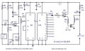
Sound to light circuit using 230 Volts lamps

Thread Starter

nikhilsonar29

Joined Sep 26, 2014
68
@eric sir
here i am having a little problem with attached musical circuit,i am making this project just for my personal interest,
Plz find the attached file,"
problem is:- plz tell me value of diode D3,actually as per symbol D3 is zener diode,but "IN4007" is simple diode,so i am confuse about it
and also ,cmos ic need low power supply i.e.5 to 12 volt,but as in diagram we are giving 230 volt suply through diode ,so is it really step down at that level,
Is the circuit is correct,as this circuit works on directlly 230 soplz give me guideline.and about that "zener diode" exact value.
Thanx and Regards
Nikhil sonar
 

Attachments

bertus

Joined Apr 5, 2008
22,956
Hello,

May I remind you that circuits that are directly powered from the mains are forbidden over here.
See the Terms of Service section 6.

Please use a transformer to power the chaser and an optocoupler like the MOC-series for the triac.

Bertus
 

bertus

Joined Apr 5, 2008
22,956
Hello,

There are many dangerous circuits on the web.
The one you are showing is one of them.
All parts in the circuits are directly connected to the mains and will shock you when touched.

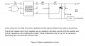
Here is a typical circuit to isolate the outputs with a MOC:


For powering the chaser, a DC adapter can be used ( 5 to 12 Volts DC will do) .

Bertus
 

Attachments

Last edited:

Thread Starter

nikhilsonar29

Joined Sep 26, 2014
68
sory to say but dnt get your idea sir,
do i implement this circuit with in my musical circuit? ,or this is just for the idea,
and as my lamp needed \ 230 volt ac,and if use transformer then how can bulb will get supply of 230v,
plz sir if possible give me electrical connection dig of "trf" with the existing musical circuit.
Thanx and Regards
NIkhil
 

bertus

Joined Apr 5, 2008
22,956
Hello,

The following thread will give you circuits for powering the chaser:
Regulated wall adapters

The MOC circuits can be connected to the output of the 4017 with a resistor (to regulate the led current of the opto coupler) to the + of the powersupply.

Bertus
 

ericgibbs

Joined Jan 29, 2010
21,487
hi,
For safety it is recommended that you power the 'electronics module' using a isolated power supply, say 12Vdc.
A simple 9Vdc or 12Vdc 'wall wart' at 500mA would be a simple solution.

Use Bertus post #109 circuit to drive the mains powered lamp.

The circuit shows D3 diode as a 1N4007 and but it is drawn as a Zener diode, so there is NO voltage clamp limit on the DC line.

Eric
 

Thread Starter

nikhilsonar29

Joined Sep 26, 2014
68
and i have confirm that D3 is zener diode as voltage stabilizer ,D3 is 12 volt and half watt zener diode.
i think direct that circuit will also work.
 

Thread Starter

nikhilsonar29

Joined Sep 26, 2014
68
ok sir i get the idea,
but for each bulb i need to have separate moc2030,which is of approx "1" dollar cost,
then circuit will be much costlier ,
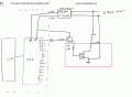
and plz find the attachments,
1)vcc of moc3020 is corresponds to o/p of ic 2,right?
 

Attachments

ericgibbs

Joined Jan 29, 2010
21,487
hi,
The MOC3020 requires a maximum emitter diode current of 30mA according to the datasheet.
I expect a typical value would be 20mA.
So to calculate the series resistor for the emitter, is driving voltage minus ~1.8Vdiode drop divided by 20mA.
For a 12V drive source, that is 12-1.8 = 10.8v/0.02 = 540R, say 470R or 560R.

You will not be able to get 20mA at 12V from the output pin of a 4017, so a buffer transistor for each MOC input drive will be required.

E
 

AnalogKid

Joined Aug 1, 2013
12,181
and i have confirm that D3 is zener diode as voltage stabilizer ,D3 is 12 volt and half watt zener diode.
i think direct that circuit will also work.
You are correct, D3 should be a zener diode. But with a 230 VAC input it will be dissipating almost 0.4 W, so use a 1 W diode. Also, C3 is too small. At 1000 uF, the ripple will be around 6 V, way too much. Increase C3 to 1000 uF.

ak
 

donpetru

Joined Nov 14, 2008
185
Why you don't try to build a lighting circuit powered from 9...24V with a transformer? It is much safer such circuit, for example:
 

Thread Starter

nikhilsonar29

Joined Sep 26, 2014
68
thanks all
@bertus sir i will try your sound chaser circuit with isolation,
and orga de lumini circuit i will also try "ORGA DE LUMINI" @donpertu sir
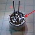
one more que sir about condenser mike
plz find the attachments
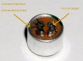
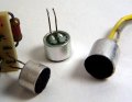
i am using that condenser mike ,firstly i was checking for polarity of condenser mike(using DMM "continuity"),and i found that it was already short.
i dont know i am checking right or wrong
and plz tell me which condenser mike should i use,because i circuit they dont have explain anything about it(config)
Thanks and Regards
nikhil
 

Attachments

Top