 Facebook
 Google
 GitHub
 Linkedin
Hello, Im new to EE.
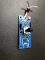
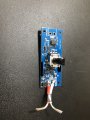
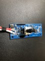
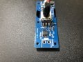
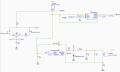
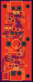
Recently, I designed a LED driver and dimmer circuit and ordered the PCB. Im using a TLC555 for PWM and a LM3405 as the driver. I have soldered on everything and double checked continuity and everything seems to be fine. But when I run 5V through with a powerbank and put a multimeter in current mode on the other end where the LED is supposed to be, I don't get any readings. I haven't received the LED yet which is why I used a multimeter to complete the circuit. I think there are 2 possible sources of error: Either I fried a component while soldering, which is unlikely because I made 2 boards. The other reason is that there is something fundamentally wrong with my circuit design.
Recently, I designed a LED driver and dimmer circuit and ordered the PCB. Im using a TLC555 for PWM and a LM3405 as the driver. I have soldered on everything and double checked continuity and everything seems to be fine. But when I run 5V through with a powerbank and put a multimeter in current mode on the other end where the LED is supposed to be, I don't get any readings. I haven't received the LED yet which is why I used a multimeter to complete the circuit. I think there are 2 possible sources of error: Either I fried a component while soldering, which is unlikely because I made 2 boards. The other reason is that there is something fundamentally wrong with my circuit design.
Attachments
-
 1.6 MB Views: 10
 -
 1.7 MB Views: 11
 -
 1.6 MB Views: 11
 -
 1.6 MB Views: 17
 -
 309 KB Views: 17
 -
 208.6 KB Views: 17


