Solving two parralel RC circuits in Series

Thread Starter

BeginnerCircuit

Joined Jun 11, 2019
3
Hello guys,

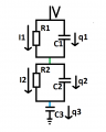
for quite some time I try to solve my problem now, but I cannot figure out the solution. I attached the schematic and hope to get some help with my questions.

How does the charge and discharge curve over time in the green and blue nodes look like? Is there an analytical equation?
I think I can solve the equations if there is only one rc circuit connected to the capacitor, but the second one confuses me too much.

I know that I can use Kirchofs laws and I get the following equations:
V1=R1*I1=Q1/C1
V2=R2*I2=Q2/C2
V3=Q3/C3
With q=dQ/dt, the other equations I get are:
q3 = I1+q1
q3 = I2+q2
(Here I don't know if I have defined the current flow correctly)

I also know that
V=V1+V2+V3

But now i am stuck. I don't know how to get my differential equations which I would need to solve for my voltage over time response.

Can anyone of you help me? What am I missing?

Thank you for help and best regards.
 

Attachments

WBahn

Joined Mar 31, 2012
30,058
You haven't defined your voltage polarities explicitly, so we are left to guess what they are from the equations and assume that you have done them correctly. But engineering isn't about guessing, so you really need to annotate your diagram with both your currents and your voltages, being sure to indicate the polarities of each.

While you are using q1 as a current, the variable 'q' is usually used for charge. You should use 'i' instead. Upper case variable names generally represent static (DC) quantities while lower case variable names represent changing quantities. It's good to be consistent with convention unless there's a really good reason not to.

So I would recommend variable names like i_R1, i_R2, i_C1, i_C2, and i_C3. I would label the nodes from top to bottom as 1, 2, 3, and 0 (the gnd). Then you have voltages drops across the stages of v_12, v_23, and v_30 (which can also be written as just v_3 since, by convention, single-subscript voltage labels are the voltage at the subscripted node relative to the common reference point).

Since you are looking for a differential equation to come out of this, you need to include the differential expressions in your work.

q = C·v (where q is the charge on C when the voltage across it is v)

i = dq/dt = C·dv/dt
 

Thread Starter

BeginnerCircuit

Joined Jun 11, 2019
3
Thank you for your reply.

I attached another diagramm where I added your comments.

I assume a dc voltage supply-

With the equations:
\(V = v_{12} +v_{23} +v_{30} \quad (1)\)
\(v_{12}=i_1\cdot R_1=q_1/C_1 \quad (2)\)
\(v_{23}=i_2\cdot R_2=q_2/C_2 \quad (3)\)
\(v_{23}=q_3/C_3\)
and
\(\frac{dq_3}{dt}=i_1+\frac{dq_1}{dt} \quad-with (2)>\quad \frac{dq_1}{dt}=\frac{dq_3}{dt}-\frac{q_1}{R_1\cdot C_1} \quad (4a) \quad <-> \frac{dq_1}{dt}+\frac{q_1}{R_1\cdot C_1} = \frac{dq_3}{dt} \quad (4b) \)
\(\frac{dq_3}{dt}=i_2+\frac{dq_2}{dt}\quad -with (3)>\quad \frac{dq_2}{dt}=\frac{dq_3}{dt}-\frac{q_2}{R_2\cdot C_2} \quad (5a) \quad <-> \frac{dq_2}{dt}+\frac{q_2}{R_2\cdot C_2} = \frac{dq_3}{dt} \quad (5b) \)

with the derivative of (1) and because the of the dc voltage the equation is as follows:
\(0=\frac{dq_1}{dt}\cdot\frac{1}{C_1}+\frac{dq_2}{dt}\cdot\frac{1}{C_2}+\frac{dq_3}{dt}\cdot\frac{1}{C_3}\)
Plugin in (4a) and (5b) leads to:
\( (\frac{1}{C_1}+\frac{1}{C_3})\frac{q_2}{R_2\cdot C_2}+(\frac{1}{C_1}+\frac{1}{C_2}+\frac{1}{C_3})\frac{dq_2}{dt}-\frac{q_1}{R_1\cdot (C_1)^2} \quad (6)\)
Plugin in (5a) and (4b) to:
\( (\frac{1}{C_2}+\frac{1}{C_3})\frac{q_1}{R_1\cdot C_1}+(\frac{1}{C_1}+\frac{1}{C_2}+\frac{1}{C_3})\frac{dq_1}{dt}-\frac{q_2}{R_2\cdot (C_2)^2} \quad (7)\)

Assuming I did everything correctly until now, would these two equations be my differential equations I would need to solve?

I hope I met all conventions now and thank you again for your help.
 

Attachments

Thread Starter

BeginnerCircuit

Joined Jun 11, 2019
3
Hi, it seems that the problem is too difficult for an analytic solution. Maybe I need to go a different way then. Can you please delete this thread? Because I am a new member I am not able to do this. Thanks for your help!
 

RBR1317

Joined Nov 13, 2010
714
Hi, it seems that the problem is too difficult for an analytic solution. Maybe I need to go a different way then.
It has been a while, but I don't remember ever using differential equations for circuit analysis again after being introduced to the Laplace transform. It is rather easy to determine the node voltages at t=0+ and at t=∞ but in between one needs a symbolic algebra engine like Maple to handle the nodal analysis in the complex frequency domain, and then the inverse Laplace transform of the node voltages. See attached images of the Maple screen. Also included is a time domain plot of the node voltages for sample component values of R1=10K, R2=20K, C1=100μF, C2=100μF, C3=300μF.
 

Attachments

WBahn

Joined Mar 31, 2012
30,058
Hi, it seems that the problem is too difficult for an analytic solution. Maybe I need to go a different way then. Can you please delete this thread? Because I am a new member I am not able to do this. Thanks for your help!
In general, we do not delete posts or threads unless they violate the ToS/UA in a manner that requires it.
 

WBahn

Joined Mar 31, 2012
30,058
Thank you for your reply.

I attached another diagramm where I added your comments.

\( (\frac{1}{C_1}+\frac{1}{C_3})\frac{q_2}{R_2\cdot C_2}+(\frac{1}{C_1}+\frac{1}{C_2}+\frac{1}{C_3})\frac{dq_2}{dt}-\frac{q_1}{R_1\cdot (C_1)^2} \quad (6)\)
Plugin in (5a) and (4b) to:
\( (\frac{1}{C_2}+\frac{1}{C_3})\frac{q_1}{R_1\cdot C_1}+(\frac{1}{C_1}+\frac{1}{C_2}+\frac{1}{C_3})\frac{dq_1}{dt}-\frac{q_2}{R_2\cdot (C_2)^2} \quad (7)\)

Assuming I did everything correctly until now, would these two equations be my differential equations I would need to solve?
It's been a long time (like thirty years) since I worked directly with differential equations. I don't see anything wrong (other than these are not actually equations, but expressions -- just an oversight on your part), but I was expecting three equations since there are three reactive elements and three independent initial conditions (which you have not stated, by the way). I do see that you are exploiting the fact that the sum of the current in the top two components and the sum of the current in the middle two components must both be equal to the current in the bottom component, and perhaps that constraint is sufficient to eliminate the third equation. But that would still seem to indicated that you can solve these two equations for q1 and q2 without ever having to take into account C3 or the initial voltage on C3. I find that troubling because if I set the initial voltage on C3 equal to the supply voltage, then the system starts out in steady state and no current flows at any time.
 

MrAl

Joined Jun 17, 2014
11,480
Hi,

I see a possible problem here.
That is, the type of voltage source is not given, or did i miss that somewhere?
Surely it can not be a unit step or any step, because the three caps in series would draw infinite current unless they just happened to be already charged to the exact voltage as the step.
 

RBR1317

Joined Nov 13, 2010
714
Surely it can not be a unit step or any step, because the three caps in series would draw infinite current...
Since when is a theoretical voltage source incapable of delivering infinite current?

When I see a voltage source labeled only "V" then it could be a constant DC source, or a switched DC source, or a constant AC source with RMS value of V.

In this case a constant DC source would be trivial, while a constant AC source would not lead to a solution using differential equations. So my somewhat limited experience leads me to believe "V" is a switched DC source. It would have been better for the TS to state the complete problem.
 

MrAl

Joined Jun 17, 2014
11,480
Since when is a theoretical voltage source incapable of delivering infinite current?

When I see a voltage source labeled only "V" then it could be a constant DC source, or a switched DC source, or a constant AC source with RMS value of V.

In this case a constant DC source would be trivial, while a constant AC source would not lead to a solution using differential equations. So my somewhat limited experience leads me to believe "V" is a switched DC source. It would have been better for the TS to state the complete problem.
Hi,

A switched DC source implies a step input doesnt it? So see if you can solve for the current i(t) for all time out of V with a unit step when all cap initial voltages are zero.
 

WBahn

Joined Mar 31, 2012
30,058
Hi,

I see a possible problem here.
That is, the type of voltage source is not given, or did i miss that somewhere?
Surely it can not be a unit step or any step, because the three caps in series would draw infinite current unless they just happened to be already charged to the exact voltage as the step.
While that's a very good point, mathematically it is a very solvable situation. The step voltage will deliver an impulse of charge that will result in the voltage across all three capacitors totaling up to the supply voltage. At that point the resistors will bleed the upper two and charge the bottom one until it is at the full supply voltage and the upper two are completely discharged.
 

MrAl

Joined Jun 17, 2014
11,480
While that's a very good point, mathematically it is a very solvable situation. The step voltage will deliver an impulse of charge that will result in the voltage across all three capacitors totaling up to the supply voltage. At that point the resistors will bleed the upper two and charge the bottom one until it is at the full supply voltage and the upper two are completely discharged.
Hello,

I tend to agree with that. If all three caps were the same value then we should see 1/3 of the voltage across each cap at 0+.

Well so what do you think the solution for i(t) is using Laplace Transforms and the Inverse Transform?

[LATER]
I think the problem i was having was that i assumed that too but with an impulse the two parallel resistors play a part in the solution even at t=0 or at least at t=0+.
But see what you can come up with anyway.
 
Last edited:

WBahn

Joined Mar 31, 2012
30,058
Hello,

I tend to agree with that. If all three caps were the same value then we should see 1/3 of the voltage across each cap at 0+.

Well so what do you think the solution for i(t) is using Laplace Transforms and the Inverse Transform?

[LATER]
I think the problem i was having was that i assumed that too but with an impulse the two parallel resistors play a part in the solution even at t=0 or at least at t=0+.
But see what you can come up with anyway.
For the voltages at t=0+ you don't need to take the resistors into account at all. For the current at t=0+ you do.
 

MrAl

Joined Jun 17, 2014
11,480
For the voltages at t=0+ you don't need to take the resistors into account at all. For the current at t=0+ you do.
No i meant the voltage means current through the resistors.

But try to find the i(t) using Laplace and see what you get.
 

RBR1317

Joined Nov 13, 2010
714
The step voltage will deliver an impulse of charge...
I would question the propriety of the phrase "impulse of charge". While it is true that an impulse of infinite current flows at t=0, the charge is a finite quantity. Likewise, none of that impulse of current flows through the resistors. Current flow through the resistors is limited by Ohm's Law and the step value of the input voltage. So the total charge that could possibly flow through the resistors is Q=(V/R)·∆t, but the actual time from t=0 to t=0+ equals zero. So with zero charge transferred through the resistors, there is no current through the resistors at t=0. Resistor current starts at t=0 yet no part of the current impulse flows through the resistors. (Any part of an infinite quantity must also be infinite.)
 

WBahn

Joined Mar 31, 2012
30,058
I would question the propriety of the phrase "impulse of charge". While it is true that an impulse of infinite current flows at t=0, the charge is a finite quantity. Likewise, none of that impulse of current flows through the resistors. Current flow through the resistors is limited by Ohm's Law and the step value of the input voltage. So the total charge that could possibly flow through the resistors is Q=(V/R)·∆t, but the actual time from t=0 to t=0+ equals zero. So with zero charge transferred through the resistors, there is no current through the resistors at t=0. Resistor current starts at t=0 yet no part of the current impulse flows through the resistors. (Any part of an infinite quantity must also be infinite.)
I'll cheerfully agree that the proper phrasing would be something like, "At t=0 the step change in voltage causes the voltage supply to deliver a current impulse that transfers sufficient charge to the capacitors so as to bring them from their initial voltages to a total voltage equal to the supply voltage."

I never said that any of that impulse goes through the resistors. But at t=0+ the resistors have a voltage across them and so current flows through them.
 
Top