Facebook
 Google
 GitHub
 Linkedin
Hi,
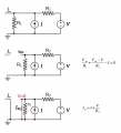
I've worked through the attached problem as best I can. The goal of the problem is to find the Thevenin's equivalent of the network and graph its i-v relationship.
I have 3 questions, and they are clearly marked on my work as Q1, Q2, and Q3, but the first two are very similar questions.
Q1: Is it correct to take out R2? I assumed no current would flow across it without a driving voltage. (My other idea would be that there would actually be some current, and it would be i3, which branches from i2", such that i2" = i3 + i4, where i3 splits to the right at the bottom of R1, and i4 returns to the left at the bottom of R1.)
Q2: Is it correct to take out R2 here? I assumed no current would go through it as Isc" would take all the current from current source, I.
Q3: Does this i-v relationship graph make sense?
Attachments
-
1.4 MB Views: 17