[solved] Pendulum - How to calculate the time it takes to go from A to B?

Thread Starter

atferrari

Joined Jan 6, 2004
5,031
Being an ideal pendulum, oscillating in a ideal 2D plane, I understand I do not need to complicate things. Still waiting if @mvas does answer my last question.

Thanks for your time and interest to reply.
 

Mark Hughes

Joined Jun 14, 2016
409
@atferrari -- I just found an amazing math animation. Doesn't answer your question exactly -- but it's totally worth the watch:

Now -- to your question. Unless this is coming out of an upper-division physics textbook we can assume it's a ideal planar pendulum ascribing to small-angle approximations. Further -- it's likely a problem in ratio reasoning, rather than a problem in physics.
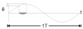
upload_2019-4-10_18-19-26.png
So -- 15° is 100% amplitude, 12° is 80% of that.
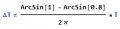
Use arcsin to find out the difference between 1 and 0.8 -- the ratio between that number and a full cycle (2pi) is proprotional to the ratio of the sample period to the total period.

Now -- it's late, and I could be wrong, but I'm going to offer this:
upload_2019-4-10_18-27-24.png
 

Thread Starter

atferrari

Joined Jan 6, 2004
5,031
@atferrari -- I just found an amazing math animation. Doesn't answer your question exactly -- but it's totally worth the watch:

Now -- to your question. Unless this is coming out of an upper-division physics textbook we can assume it's a ideal planar pendulum ascribing to small-angle approximations. Further -- it's likely a problem in ratio reasoning, rather than a problem in physics.
View attachment 174714
So -- 15° is 100% amplitude, 12° is 80% of that.
Use arcsin to find out the difference between 1 and 0.8 -- the ratio between that number and a full cycle (2pi) is proprotional to the ratio of the sample period to the total period.

Now -- it's late, and I could be wrong, but I'm going to offer this:
View attachment 174715
Now I got time to look at this. Rusty me, had to revise the basics. @Mark Hughes Thanks. I will revert.
 

Mark Hughes

Joined Jun 14, 2016
409
@atferrari,

Back when I was getting my degree in Physics, the internet wasn't really a thing -- so I relied on the books called Shaum's outlines. Here's a link: https://www.google.com/search?q=schaums+outline+physics

I had a library of these things and they had thousands of solved problems. What you learn from all of these books is that professors and textbook authors are rarely original -- they just repurpose the same questions and change the scenario slightly. They are references -- like dictionaries. But if you flip through them a bit like a book, it will you build a repository of information you can draw from. "Oh -- this problem is like the one on page 60, etc..."

If you buy those books from Abebooks.com or other resellers, you can own them for the cost of a cup of coffee.
 

SamR

Joined Mar 19, 2019
5,542
I was going to point you to the wonderful Foucault Pendulum at the Smithsonian Museum. However: "The Foucault pendulum which was displayed for many years in the Smithsonian's National Museum of American History was removed in late 1998 to make room for the Star-Spangled Banner Preservation Project and there are no current plans to reinstall it." It was nice while it lasted...
 

Thread Starter

atferrari

Joined Jan 6, 2004
5,031
@atferrari -- I just found an amazing math animation. Doesn't answer your question exactly -- but it's totally worth the watch:

Now -- to your question. Unless this is coming out of an upper-division physics textbook we can assume it's a ideal planar pendulum ascribing to small-angle approximations. Further -- it's likely a problem in ratio reasoning, rather than a problem in physics.
View attachment 174714
So -- 15° is 100% amplitude, 12° is 80% of that.
Use arcsin to find out the difference between 1 and 0.8 -- the ratio between that number and a full cycle (2pi) is proprotional to the ratio of the sample period to the total period.

Now -- it's late, and I could be wrong, but I'm going to offer this:
View attachment 174715
Hola @Mark Hughes

I spent many hours thinking of something like you propose but I failed to realize that T (period) involves 2PI rad !!
 
Last edited:

Mark Hughes

Joined Jun 14, 2016
409
@atferrari,
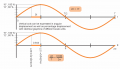
Let me see if breaking it up into two graphs helps my admittedly hurried original description (in case someone stumbles on this thread later). As you said T = 2 Pi radians -- So the basis of your solution is based on that fact -- if you can figure out the angular displacement, you can relate that to the time interval pretty quickly. So, ArcSin is used to determine the angular displacement, and then it's a ratio problem (equation shown in graphic). upload_2019-4-13_18-45-7.png
 
Last edited:

Mark Hughes

Joined Jun 14, 2016
409
One other thing -- if this problem shows up on your test with different values, solve it this way. If the professor changes the problem type and asks you to calculate the change in speed from 13°-15°, abandon this approach and use conservation of energy.
 

Thread Starter

atferrari

Joined Jan 6, 2004
5,031
One other thing -- if this problem shows up on your test with different values, solve it this way. If the professor changes the problem type and asks you to calculate the change in speed from 13°-15°, abandon this approach and use conservation of energy.
Oh no, Mark, at 72++, I am not a pupil, student or whatever anymore. :) It is me now, who propose these problems to myself, thinking of implementing a pendulum for a proof of concept in a near future.

Thanks for the help.
 
Last edited:

Thread Starter

atferrari

Joined Jan 6, 2004
5,031
@atferrari What is your project? Do we need to do the actual math instead of using this gross estimation? I made the assumption this was homework rather than a practical application.
I intend to implement a pendulum whose period could be adjusted by changing its center of mass while in motion.

Thinking of applying the push of an electromagnet at the point of extreme amplitude (as in a swing), I started to wonder about where (in time) I should locate the sensor to trigger the push. To ensure that the elapsed time would fall in the middle of a single 16 bits calculation I wanted a ballpark estimate, thus my query.

Sorry for wasting your time in such a trivial thing. I appreciate the time you dedicated to reply in detail. It is shamefully simple now!! Gracias.
 

Mark Hughes

Joined Jun 14, 2016
409
Sorry for wasting your time in such a trivial thing. I appreciate the time you dedicated to reply in detail. It is shamefully simple now!! Gracias.
Not at all. Whether or not a problem is "simple" depends on past experiences, how much sleep you've had that night, and whether or not there is a screaming baby or barking dog in the other room. In short -- a problem I solve today I might not be able to solve yesterday, or tomorrow. That's why it's important to have forums like this.

Good luck with your project!

Take care!
Mark
 

djsfantasi

Joined Apr 11, 2010
9,237
While calculating the desired position may be fun, in my experience it is frustrating because of unanticipated external forces. I always end up using an iterative process anyway. If I design for and begin the iterative process right away, thus skipping all the calculations, I get my desired result much quicker.

In one example, I created a circuit that used an audio track and moved an animatronic mouth in sync and with a variable amplitude following the audio signal.

The unexpected external forces included software delays and delays introduced by the envelope follower in hardware. The mouth could be seen moving to the audio track but with a noticeable delay.

I could have directly measure the time in microseconds that the processing took. And I could calculate the RC delay time. But I didn’t.

I used Audacity to develop my audio tracks. So, with hand-on-mouse, I chose a easy-to-distinguish time as a starting event, played the tracks and clicked the mouse to mark the track time when the mouth moved to that event. I also could have created a disposable audio track with Audacity

First time, I had my answer. By shifting the audio track to start 30ms after the control track, sound and movement appeared to be totally synchronized.

In your case, if you can design the mounting for the sensor so that physical adjustments can be made, I’d start anywhere in the vicinity of where you think it should be. Then after watching the system react for a while, move the sensor in the indicated direction.

As is written on bottles of shampoo - Lather, Rinse and Repeat. You can even use a temporary mount and only create the permanent mount after you have the correct dimensions nailed down.

Personally, I use Velcro in my temporary mounts, as adjustments can be made easy. Sometimes, I use it in a permanent mount. My prop sports scoreboard had all of its electronics mounted with Velcro.

I get Industrial Velcro, as it’s adhesives and holding power are excellent. The only problem with Velcro is that it does not adhere well to latex paint nor fabric.

If you enjoy the calculations, after you determine the location this way, try to verify it through math.
 

MrAl

Joined Jun 17, 2014
13,859
Hi,

For numerical solving the following set of ODE's helps:


dA/dt=dA(0)/dt
dA^2/dt^2=-w^2*sin(A)

and in more complete form where it is more obvious that A(t) is a function (A=Theta=angle):
dA(t)/dt=dA(0)/dt
dA(t)^2/dt^2=-w^2*sin(A(t))

where:
A(t) is the angle function,
dA(0)/dt is the initial value of the first derivative,
There are actually some symbolic solutions for 't' to this too depending on the initial values.
I'll see if i can dig up some more on this. Havent looked at this in years now but it's a good example for comparing numerical methods. I used RK45 in the past and the numerical solution comes out pretty accurate.
 
Top