
 Facebook
 Google
 GitHub
 Linkedin
[Solved] HV Motor Control - Snubbers, Flyback Diode Possibly Insufficient
- Thread starter Ri5ux
- Start date

Scroll to continue with content

Kjeldgaard
- Joined Apr 7, 2016
- 476
First, I would say that is a really nice prototype!
But how are the probes of the oscilloscope connected, and especially the ground/common connections?
But how are the probes of the oscilloscope connected, and especially the ground/common connections?
Thank you! The ground of the probes are connected to the source of the MOSFET (B-), without ground springs or any inductance preventing adapters. Channel one is simply directly probing the gate of the MOSFET, and channel two is directly probing the drain. I should probably create a ground spring, unless there is a better recommendation than that.First, I would say that is a really nice prototype!
But how are the probes of the oscilloscope connected, and especially the ground/common connections?
EDIT: I'm going to mess around with the probes and see how much of the overshoot is caused by bad probe connection.
Last edited:
Pedant Engineer
- Joined May 27, 2018
- 256
I gotta say you posting waveforms like this makes it so much easier. What kind of CRO do you have BTW. My older tectronix can do this but damn it is a hassle.I believe I see what you're talking about. Channel 1 is the drain, Channel 2 is the gate. You're referencing the section of the waveform where it begins to ripple and fade off, correct?

Additionally here's the turn off. The part where the drain begins to overshoot is when the drain current goes down, so the voltage rises, right? I noticed as the drain voltage falls after the first rise, the gate voltage also rises. Why is that?

You can see in both traces where the gate voltage plateaus. That is the main part of the switch transition. It is a little harder to see in the first plot and very clear in the second.
In the first plot, the ringing starts when the drain voltage falls but as the mosfet is going to a lower and lower resistance the ringing is damped / clamped. It may not be evident in the voltage waveform at that point but it may still be apparent in the current waveform. You'd need a current probe or a well placed current shunt to see that if it is actually there.
In the second plot the ringing on the drain doesn't start till the mosfet is as good as off so it does not dampen the ringing any more and the energy in the parasitic inductances charged with the drain current then setup a charged tank circuit with the parasitic capacitances. The ringing on the gate waveform as it goes below the gate threshold voltage is partly an artifact and partly the result of the mosfet capacitance between drain and gate (otherwise known as the Miller or feedback capacitance) and it is the same capacitance that causes the plateau in the first place. As the mosfet turns on, the drain voltage comes down which, via the Miller cap also pushes the gate voltage back down and counteracts the gate voltage coming up which caused it in the first instance. So it is a feedback mechanism and very useful for calculating the switching time of the mosfet because it is usually so easy to see on a CRO and does not need a high voltage probe on a drain pin.
I just re read your question and i think I see what you mean, the drain and gate waveforms are 180deg out of phase. That suggests the mosfet is not actually turned off completely and given where it is in the waveform makes me a bit suspicious of the mosfet. the artifact you are talking about appears to exist from 5V to 2.5V where it has a glitch of some kind. There is also a lower frequency ringing going on there which will likely be an artifact of the layout. I wouldn't get too worried about those things just yet but I would like to see those parts of the waveforms closer up if you have the energy. Or do that later, if and when snubbers are required.
Some mosfets of this size are not actually a single die and that can lead to some very weird issues. Do you know if this is a single die part? The data sheets often won't say so you may have to ask the manufacturer about the part.
We need to lower the parasitic inductance effect that is causing the ringing. If I read your layout correctly, the freewheeling diode is about half way between the output connector and the mosfet drain. Is that right? If so, do you have another diode you could use as a freewheeling diode but placed much closer to the mosfet drain and to the bulk caps as close as possible to the mosfet? It does not need to be pretty or a long term solution, it is an experiment to determine the location of the parasitic inductance (I believe is in the bus bars mostly). So any fast diode that won't go bang is fine. The switching time is around 350ns so your options are wide open in the fast diode area.
If anything I say is teaching grandma to suck eggs please let me know. I want to be complete in my explanations but I don't want to insult you in the process.

Pedant Engineer
- Joined May 27, 2018
- 256
Excellent! Another member who appreciates good practice is a good idea.Moving that resistor closer to the MOSFET gate itself didn't change much. I couldn't visually detect any changes on the scope, but at least it's there now for good practice.
The benefit of the correct placement may or may not become apparent when the drain voltage and current gets to proper levels. In the meantime, as you say, good practice.
When you are done with the experiment to locate the stray inductance there are other experiments to check if the ringing is real. It can sometimes be (in part) an artifact of CRO connections, grounding points and loop currents in the mains (earth) connections of your device and CRO. But for now, my guess is there is a parasitic L that needs be found.
Kjeldgaard
- Joined Apr 7, 2016
- 476
It sounds like you have the right understanding of oscilloscope probes and short connections.Thank you! The ground of the probes are connected to the source of the MOSFET (B-), without ground springs or any inductance preventing adapters. Channel one is simply directly probing the gate of the MOSFET, and channel two is directly probing the drain. I should probably create a ground spring, unless there is a better recommendation than that.
EDIT: I'm going to mess around with the probes and see how much of the overshoot is caused by bad probe connection.
I just had to search for "Ground Spring" and it was a known gizmo.
The best part about this oscilloscope is that I can connect it to my PC via a USB port, open up EasyScopeX, and capture the screen or control the oscilloscope from the PC. You can also save the screenshots to a flash drive (that you plug into the oscilloscope) instead. It's a Siglent SDS1102CML. So far, worth every cent I paid for it.I gotta say you posting waveforms like this makes it so much easier. What kind of CRO do you have BTW. My older tectronix can do this but damn it is a hassle.
You can see in both traces where the gate voltage plateaus. That is the main part of the switch transition. It is a little harder to see in the first plot and very clear in the second.
In the first plot, the ringing starts when the drain voltage falls but as the mosfet is going to a lower and lower resistance the ringing is damped / clamped. It may not be evident in the voltage waveform at that point but it may still be apparent in the current waveform. You'd need a current probe or a well placed current shunt to see that if it is actually there.
In the second plot the ringing on the drain doesn't start till the mosfet is as good as off so it does not dampen the ringing any more and the energy in the parasitic inductances charged with the drain current then setup a charged tank circuit with the parasitic capacitances. The ringing on the gate waveform as it goes below the gate threshold voltage is partly an artifact and partly the result of the mosfet capacitance between drain and gate (otherwise known as the Miller or feedback capacitance) and it is the same capacitance that causes the plateau in the first place. As the mosfet turns on, the drain voltage comes down which, via the Miller cap also pushes the gate voltage back down and counteracts the gate voltage coming up which caused it in the first instance. So it is a feedback mechanism and very useful for calculating the switching time of the mosfet because it is usually so easy to see on a CRO and does not need a high voltage probe on a drain pin.
I just re read your question and i think I see what you mean, the drain and gate waveforms are 180deg out of phase. That suggests the mosfet is not actually turned off completely and given where it is in the waveform makes me a bit suspicious of the mosfet. the artifact you are talking about appears to exist from 5V to 2.5V where it has a glitch of some kind. There is also a lower frequency ringing going on there which will likely be an artifact of the layout. I wouldn't get too worried about those things just yet but I would like to see those parts of the waveforms closer up if you have the energy. Or do that later, if and when snubbers are required.
Some mosfets of this size are not actually a single die and that can lead to some very weird issues. Do you know if this is a single die part? The data sheets often won't say so you may have to ask the manufacturer about the part.
We need to lower the parasitic inductance effect that is causing the ringing. If I read your layout correctly, the freewheeling diode is about half way between the output connector and the mosfet drain. Is that right? If so, do you have another diode you could use as a freewheeling diode but placed much closer to the mosfet drain and to the bulk caps as close as possible to the mosfet? It does not need to be pretty or a long term solution, it is an experiment to determine the location of the parasitic inductance (I believe is in the bus bars mostly). So any fast diode that won't go bang is fine. The switching time is around 350ns so your options are wide open in the fast diode area.
If anything I say is teaching grandma to suck eggs please let me know. I want to be complete in my explanations but I don't want to insult you in the process.
You're thinking the MOSFET also isn't completely turning off? Perhaps my pull down resistor is not sufficient. Before the gate resistor, back on the control board, right after the driver output, I have a 100K Ω resistor pulling the output down to ground. Perhaps it needs to be a lower value (80K Ω?). I can grab a screenshot of the lower frequency ringing as well here in a bit.
I know this MOSFET is a dual MOSFET module, but I have no idea if it has multiple dies or not. I'm willing to bet we won't find that information either (without ripping them to shreds). The company that made this MOSFET (Advanced Power Technology Europe) has long since been bought out by the company Microsemi. I'm pretty sure these modules are rare/uncommon now. I found 3 on eBay for $20 each, and took a chance on them.
I have a few more of these 50ns TSOP package diodes, identical to the one installed in the controller. I'll use one of them for isolating the parasitic inductance.
Also no worries, I'm by no means a real engineer and still have a lot to learn. I'm processing everything you're saying pretty well. I've done a good amount of research on controlling inductive loads, but I'm still learning. This time last year I didn't own an oscilloscope, nor did I know about things like "parasitic inductance" or "miller capacitance". I have a habit of setting extreme goals and overcoming them, the process of building a high voltage motor controller is quite challenging, but the learning experience is definitely worth it.
And yeah, I definitely appreciate good practices. Nothing like doing it the right way
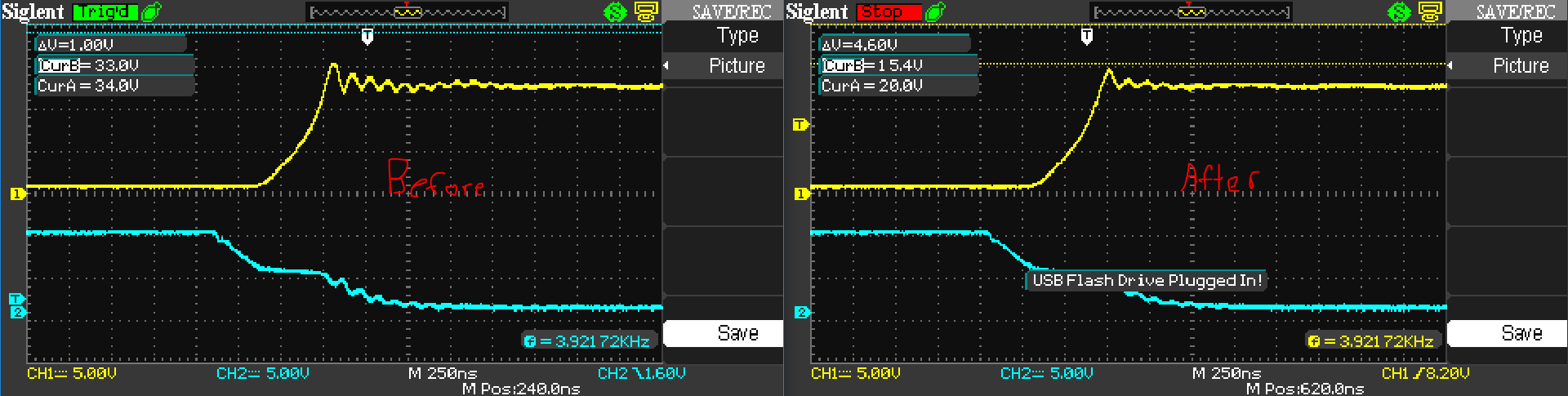
I messed around with the oscilloscope probes, took off the alligator clip ground leads, and created a little ground spring, trying to shorten that ground lead as much as possible. I probed the bus bars, and while the ringing and overshoot remained, it did slightly reduce the intensity. I'm thinking you're right on the parasitic L originating in the bus bars.
Here's a before and after shot:
The groundspring:

I'll get to that low frequency waveform and diode testing now.
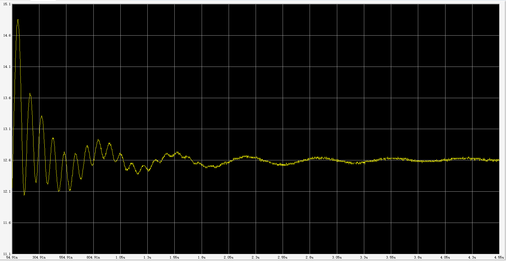
Is this the screenshot you were looking for (low frequency ring)?Excellent! Another member who appreciates good practice is a good idea.
The benefit of the correct placement may or may not become apparent when the drain voltage and current gets to proper levels. In the meantime, as you say, good practice.
When you are done with the experiment to locate the stray inductance there are other experiments to check if the ringing is real. It can sometimes be (in part) an artifact of CRO connections, grounding points and loop currents in the mains (earth) connections of your device and CRO. But for now, my guess is there is a parasitic L that needs be found.
High Res Version: http://arisux.com/upload/uploads\LowFrequencyRing.png
Low Res Version
Pedant Engineer
- Joined May 27, 2018
- 256
You are a dream to work with! For a non engineer (or even an engineer in all too many cases) you are doing extremely well and clearly are a quick learner.Is this the screenshot you were looking for (low frequency ring)?
High Res Version: http://arisux.com/upload/uploads\LowFrequencyRing.png
Low Res Version
The plot is fantastic but not quite what I meant. I was interested in the high frequency ringing on the drain and the gate together and with expanded timebase to better see the phase relationship between them. When the gate voltage falls below Vgt the two waveforms should be in phase. The fact that they did not appear to be in phase may be an artefact of the CRO (they all can do that) or an external influence that interacts with the signals (such as a ground loop).
Be careful with that ground spring. And when you get to higher voltages also don't forget your CRO is earthed. It is a messy splat.
Thank you for the compliment!You are a dream to work with! For a non engineer (or even an engineer in all too many cases) you are doing extremely well and clearly are a quick learner.
The plot is fantastic but not quite what I meant. I was interested in the high frequency ringing on the drain and the gate together and with expanded timebase to better see the phase relationship between them. When the gate voltage falls below Vgt the two waveforms should be in phase. The fact that they did not appear to be in phase may be an artefact of the CRO (they all can do that) or an external influence that interacts with the signals (such as a ground loop).
Be careful with that ground spring. And when you get to higher voltages also don't forget your CRO is earthed. It is a messy splat.
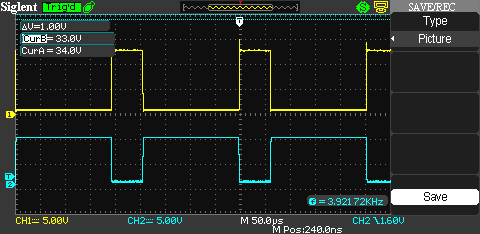
How's this? I had also taken this one earlier, forgot to post it. Hopefully this is what you meant by expanded:
If you need a different shot, no problem; however, pretty soon I'll be off for the day so it may have to wait until tomorrow.
Based on that shot, they appear to be pretty well in-phase if you ask me.
Careful I will be, be a shame if the little spring fell off onto a bus bar...yikes, don't want to think about that. Note taken on the earth connection and high voltage, I've been looking for an isolation transformer for my oscilloscope, also considered building one, but haven't come across the right transformers for that yet (without rewinding them anyways). It shouldn't be an issue if I run the controller off of batteries though, right? I've got 12 Gel batteries I plan to use it with once it's complete. Just using power supplies right now for the testing stages.
Last edited:
Pedant Engineer
- Joined May 27, 2018
- 256
LOL That's a contracted view not expanded (in my version of the words)Thank you for the compliment!
How's this? I had also taken this one earlier, forgot to post it. Hopefully this is what you meant by expanded:
If you need a different shot, no problem; however, pretty soon I'll be off for the day so it may have to wait until tomorrow.
Based on that shot, they appear to be pretty well in-phase if you ask me.
Careful I will be, be a shame if the little spring fell off onto a bus bar...yikes, don't want to think about that. Note taken on the earth connection and high voltage, I've been looking for an isolation transformer for my oscilloscope, also considered building one, but haven't come across the right transformers for that yet (without rewinding them anyways). It shouldn't be an issue if I run the controller off of batteries though, right? I've got 12 Gel batteries I plan to use it with once it's complete. Just using power supplies right now for the testing stages.
It can wait, no problem.
When you get there, please be extremely careful connecting those batteries into a high voltage supply. Batteries don't have an off switch and 12 x 12V(?) = lethal
The isolation transformer will help stop the splat from shorting out the mains but it won't stop the higher frequency currents so much so it is still possible to blow up your device with what is effectively a decoupled earth connection through your CRO lead ground. The batteries will help solve that too (but not completely). It's just the batteries introduce a new problem. More on that later. I'm done for the day also. It's late.
Hopped on quick and saw your reply, so I'll reply quick before I hit the sack.LOL That's a contracted view not expanded (in my version of the words)
It can wait, no problem.
When you get there, please be extremely careful connecting those batteries into a high voltage supply. Batteries don't have an off switch and 12 x 12V(?) = lethal
The isolation transformer will help stop the splat from shorting out the mains but it won't stop the higher frequency currents so much so it is still possible to blow up your device with what is effectively a decoupled earth connection through your CRO lead ground. The batteries will help solve that too (but not completely). It's just the batteries introduce a new problem. More on that later. I'm done for the day also. It's late.
--
Sorry haha. The wording is just a bit confusing to me. The first image is what I thought was expanded. When that wasn't right I thought the second version might have been what you meant. I might need an example
No worries, I'm taking as many precautions as I can to prevent accidental damage. The batteries may not have on/off switches, but the batteries are inline with a 450V 40A DC circuit breaker. If anything goes sideways, a few components might blow and might make a nasty mess, but the circuit breaker should (hopefully) prevent additional current from being dumped into the controller.. As for the HV power supply I have two DROK boost converters connected in series using power supplies that I isolated from each other. Those boost converters both have current limiting functionality, so that will help a lot during high voltage testing. I also use those to charge the entire set of batteries while connected (set to a 1A current limit during charging). In case you were wondering, the batteries I'm using are all identical, so they have very similar internal resistances, which should reduce any issues that may arrise from the batteries themselves. Also, yes, the batteries are 12V. The overall voltage being fed into the controller will end up being close to 165V on a full charge.
Besides, I won't be using the batteries to power the controller until I know for sure the controller is stable, just the limited power supply. I completely understand this is a dangerous project, I'm doing my best to do it the right way. Skimping out on safety is the last thing I want to do. I am entirely open to any and all advice.
Also, what problem was it that the batteries introduce? Let me know, and thanks a ton for all the help you've provided me with so far!
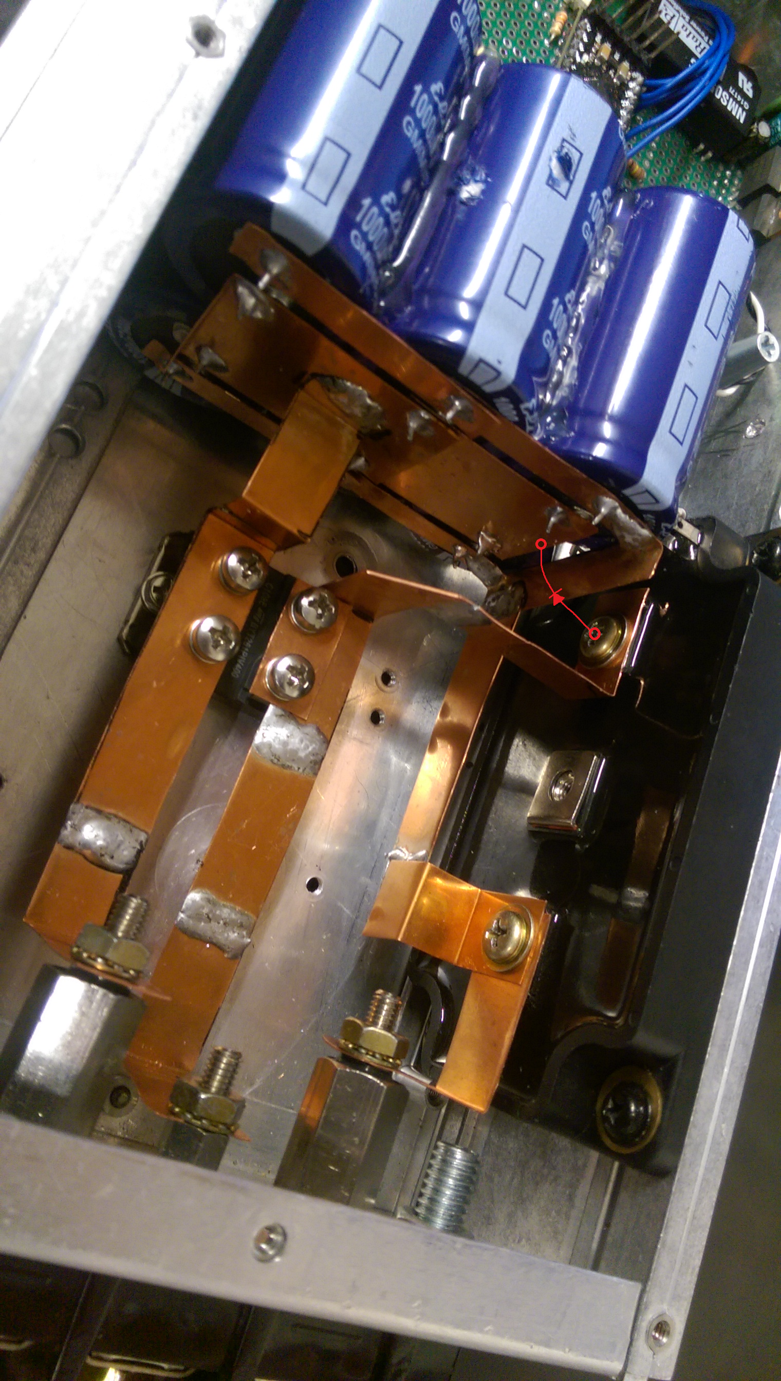
Sorry for the delay, I've just done the diode testing. For physical placement convenience, I used a Vishay UF5408 diode instead of one of my spare BYT261PIV-100's. This allowed me to place the diode directly on the Drain of the MOSFET, and to the closest annode of the capacitor bank like so:We need to lower the parasitic inductance effect that is causing the ringing. If I read your layout correctly, the freewheeling diode is about half way between the output connector and the mosfet drain. Is that right? If so, do you have another diode you could use as a freewheeling diode but placed much closer to the mosfet drain and to the bulk caps as close as possible to the mosfet? It does not need to be pretty or a long term solution, it is an experiment to determine the location of the parasitic inductance (I believe is in the bus bars mostly). So any fast diode that won't go bang is fine. The switching time is around 350ns so your options are wide open in the fast diode area.
Before UF5408 Diode:

After UF5408 Diode:

Very noticeable difference here; significantly less ringing. This was the most effective location throughout the two bars, which makes sense. I do feel that it could be slightly better if I were to move the anode that connects to the capacitor bank into a more centered location, rather than to the left side. Thoughts?
EDIT: For some reason the oscilloscope shots won't show in the post itself, but will in the editor, and if you visit the links directly. Not sure what's up there.
EDIT 2: Fixed the photos.
Last edited:
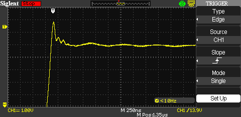
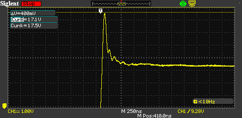
I adjusted the layout once again (just purely for testing). I removed the 6000uF capacitor bank and added one 1000uF capacitor practically right on top of the FET (should be sufficient for the motor without load), and placed the UF5408 diode right next to that and the FET. The peak voltage worsened. Now up to 17V from 15.5V with the previous layout (and UF5408 bridged across + and drain close to the FET)
Here's the waveform:
The testing layout:

I'm thinking the layout probably doesn't get much better than it was previously. That or I'm missing a concept entirely here, but I'm pretty sure this is as good as it gets with the current FET. I'm going to put the 6000uF capacitor bank back in and see what I can do about permanently moving the BYT261PIV-100 diode as close as physically possible to the FET. At this point, based on all of the information I've been provided with, I believe I need to create a snubber and place it across the load.
Here's the waveform:
The testing layout:
I'm thinking the layout probably doesn't get much better than it was previously. That or I'm missing a concept entirely here, but I'm pretty sure this is as good as it gets with the current FET. I'm going to put the 6000uF capacitor bank back in and see what I can do about permanently moving the BYT261PIV-100 diode as close as physically possible to the FET. At this point, based on all of the information I've been provided with, I believe I need to create a snubber and place it across the load.
Last edited:
Now that the layout has been improved, I decided to try increasing the gate resistor again to reduce the switching speed. This time there's no ringing from adding a higher value gate resistor. I chose a pretty high value of 150Ω. The spike has decreased to 14.4V and has rounded off quite a bit. Additionally, the remaining ringing from the layout has completely disappeared. The waveform is starting to look very acceptable compared to before. I'm going to try a few lower value resistors and see how that goes.
Attachments
-
329.1 KB Views: 6
-
329.1 KB Views: 3
-
329.1 KB Views: 4
Last edited:

Oh okay, will do that from now on. Sorry about that.
Pedant Engineer
- Joined May 27, 2018
- 256
S
With batteries in series, the problem can be if one is weak then the others will force it into reverse polarity which can be explosive, and boost converters, you have set them up well but beware of same issue: if one goes into current limit the other and the load may force it into a reverse bias situation which can also be explosive.
With the power semiconductors you are using, especially with batteries as the power source that probably have fault current ratings in the hundreds or low thousands of amps, if you have a catastrophic failure that 'blows' the semiconductor the resulting bang could make you permanently deaf. Industrial deafness is not uncommon among power electronics engineers. Besides precautions to prevent splats, hearing protection is a very good idea.
As you already know, slowing down the switch transitions will reduce the spikes at the expense of higher switching losses. But the spikes may well return when the load current comes up. My advice would be to keep the switch speed high initially and determine the snubber elements you need for your given layout then slow the transitions down again if you want to.
My 'trick' for determining the parasitics your snubber has to compensate for is simply this:
At a low operating voltage but enough current to make the ringing readily discernible, add a capacitance in the snubber location that shifts the frequency of the ringing by a factor of 5 or more. Now you could say that the ringing frequency is a function of your applied capacitance and the parasitic inductance and so you can calculate that inductance. Now remove your cap and remeasure the ringing frequency. you know the parasitic inductance and the frequency so calculate the parasitic capacitance. It is pretty simple technique but the results are damn near perfect. I don't have it patented yet so shhhh, don't tell anyone!
Your snubber cap wants to be big enough to swamp the parasitic capacitance and the resistors wants to be sized to set the damping factor to around 0.8. Trial a few resistances with the circuit still at low volts. You may be surprised that the resistor is a higher value than you may have expected. I suggest starting at 100R and see how you go. The final value might be under 10R, or more like 220R. Suck it and see is perfectly reasonable for this bit of the operation as other factors often come to light in the process as you have already found from what you have already done.
I suspect you are correct in that your original layout prior to the 1000uF experiments are about as good as it is going to get and a lot of your parasitics are an unavoidable consequence of the packages the semiconductors are in and the physical size of the capacitors etc etc.
And on that topic, how did you size the capacitor bank and what ripple current rating and frequency are you designing for? I'm just wondering if you need so much capacitance or maybe need more or better caps as brushed motors can be a bit brutal as a load I think.
You have learned a very great deal and you are absolutely correct with what you have done and your experiments. I am impressed. I have spent years in power electronics and known many engineers who don't understand it as you now do. So, enough with the admiration society ;-) and down to business:Oh okay, will do that from now on. Sorry about that.
With batteries in series, the problem can be if one is weak then the others will force it into reverse polarity which can be explosive, and boost converters, you have set them up well but beware of same issue: if one goes into current limit the other and the load may force it into a reverse bias situation which can also be explosive.
With the power semiconductors you are using, especially with batteries as the power source that probably have fault current ratings in the hundreds or low thousands of amps, if you have a catastrophic failure that 'blows' the semiconductor the resulting bang could make you permanently deaf. Industrial deafness is not uncommon among power electronics engineers. Besides precautions to prevent splats, hearing protection is a very good idea.
As you already know, slowing down the switch transitions will reduce the spikes at the expense of higher switching losses. But the spikes may well return when the load current comes up. My advice would be to keep the switch speed high initially and determine the snubber elements you need for your given layout then slow the transitions down again if you want to.
My 'trick' for determining the parasitics your snubber has to compensate for is simply this:
At a low operating voltage but enough current to make the ringing readily discernible, add a capacitance in the snubber location that shifts the frequency of the ringing by a factor of 5 or more. Now you could say that the ringing frequency is a function of your applied capacitance and the parasitic inductance and so you can calculate that inductance. Now remove your cap and remeasure the ringing frequency. you know the parasitic inductance and the frequency so calculate the parasitic capacitance. It is pretty simple technique but the results are damn near perfect. I don't have it patented yet so shhhh, don't tell anyone!
Your snubber cap wants to be big enough to swamp the parasitic capacitance and the resistors wants to be sized to set the damping factor to around 0.8. Trial a few resistances with the circuit still at low volts. You may be surprised that the resistor is a higher value than you may have expected. I suggest starting at 100R and see how you go. The final value might be under 10R, or more like 220R. Suck it and see is perfectly reasonable for this bit of the operation as other factors often come to light in the process as you have already found from what you have already done.
I suspect you are correct in that your original layout prior to the 1000uF experiments are about as good as it is going to get and a lot of your parasitics are an unavoidable consequence of the packages the semiconductors are in and the physical size of the capacitors etc etc.
And on that topic, how did you size the capacitor bank and what ripple current rating and frequency are you designing for? I'm just wondering if you need so much capacitance or maybe need more or better caps as brushed motors can be a bit brutal as a load I think.
Last edited by a moderator:
Pedant Engineer
- Joined May 27, 2018
- 256
You are very welcomeHopped on quick and saw your reply, so I'll reply quick before I hit the sack.
--
Sorry haha. The wording is just a bit confusing to me. The first image is what I thought was expanded. When that wasn't right I thought the second version might have been what you meant. I might need an example
No worries, I'm taking as many precautions as I can to prevent accidental damage. The batteries may not have on/off switches, but the batteries are inline with a 450V 40A DC circuit breaker. If anything goes sideways, a few components might blow and might make a nasty mess, but the circuit breaker should (hopefully) prevent additional current from being dumped into the controller.. As for the HV power supply I have two DROK boost converters connected in series using power supplies that I isolated from each other. Those boost converters both have current limiting functionality, so that will help a lot during high voltage testing. I also use those to charge the entire set of batteries while connected (set to a 1A current limit during charging). In case you were wondering, the batteries I'm using are all identical, so they have very similar internal resistances, which should reduce any issues that may arrise from the batteries themselves. Also, yes, the batteries are 12V. The overall voltage being fed into the controller will end up being close to 165V on a full charge.
Besides, I won't be using the batteries to power the controller until I know for sure the controller is stable, just the limited power supply. I completely understand this is a dangerous project, I'm doing my best to do it the right way. Skimping out on safety is the last thing I want to do. I am entirely open to any and all advice.
Also, what problem was it that the batteries introduce? Let me know, and thanks a ton for all the help you've provided me with so far!






