[SOLVED] Arduino R4 Minima and MAX242 Level Shifter

Thread Starter

Joester0064

Joined Jun 14, 2023
77
Hi All,

I am having an issue with the TTL output from a MAX242 (18 pin version) despite the enable pin being in a low state. I have confirmed with my oscilloscope that there are RS232 signals on the RS232 input (pin 14), but I do not see any output on the TTL side (Pin 13). The data sheet shows that the enable pin is active low which I have confirmed with a DMM that it is. Shutdown pin is floating at 0V.

I have the Arduino setup to output "RS232 comms active" each time the reset button is pressed for testing. When I do this, I receive the data and that text shows on in the tera term terminal. When I press characters on the keyboard, I can see the RS232 data present at Pin 14 but nothing on Pin 13. I am placing the oscilloscope probe directly on the pin of the IC. I have also confirmed I have the +/- 10V on pins 3 and 7 so I know the doubler and inverter are working properly.

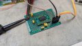
I originally breadboarded this circuit and had the same issue. I have since built a prototype board in case there was some issue with the breadboard setup. Please see attached pictures.

I have also tried 2 other new ICs of same part number with the same results. Also, I have tried this with Pin 1 floating and at 5V, in both cases the voltage on Pin 13 is 0V and there is no data present when tested. When Pin 1 is low the voltage on Pin 13 is about 3V which I assume is a good sign. I just don't see any data on it, I know I have the voltage per division down low enough to be able to see it on the scope as when I test on the TTL Tx pin (pin 12) I can see data going out to the laptop.

Any help is greatly appreciated.

Thanks!

Joe


1721070853445.png

PXL_20240715_191839979.MP.jpg

PXL_20240715_191824939.MP.jpg
 

Attachments

panic mode

Joined Oct 10, 2011
4,864
pins EN (enable) and SHDN (shut down) have a line above the label. this indicates that those signals have their state inverted. so to enable drivers, /EN would need to be connected to 0VDC (since inverted).

same goes for shutdown, to use shutdown, /SHDN need to be low. but then you don't get the transceivers working... so to allow them to work, /SHDN need to be high.
 

Thread Starter

Joester0064

Joined Jun 14, 2023
77
Thanks for the reply, I have now connected pin 18 to Vcc (5V) and have confirmed Pin 1 is low. I still have the same problem. Please see the attached scope shot. Channel on is on pin 14 and channel 2 is on pin 13.PXL_20240716_131658923.MP.jpg
 

MrChips

Joined Oct 2, 2009
34,628
Your oscilloscope screen shows incoming signal swinging from 0V to -12V. This is not right. It should be swinging to both positive and negative voltages.
 

Thread Starter

Joester0064

Joined Jun 14, 2023
77
Thank tou for the reply. Here is another shot showing the voltage swing, looks like from 200mV to -10V. Also a few more questions:

Should I not be using electrolytic caps? I don't see any on the readymade boards online, they look like they all use ceramic. Do I need a resistor from 13 to ground? Pin 13 is currently connected to the Arduino, is that not good enough or do I still need a resistor there?

I have since read that the unused output pins 8 and 10 should be grounded, I have since done this with the only difference being the random characters that now stream into the terminal.

PXL_20240716_142520692.MP.jpg
 

MrChips

Joined Oct 2, 2009
34,628
Thank tou for the reply. Here is another shot showing the voltage swing, looks like from 200mV to -10V. Also a few more questions:

Should I not be using electrolytic caps? I don't see any on the readymade boards online, they look like they all use ceramic. Do I need a resistor from 13 to ground? Pin 13 is currently connected to the Arduino, is that not good enough or do I still need a resistor there?

I have since read that the unused output pins 8 and 10 should be grounded, I have since done this with the only difference being the random characters that now stream into the terminal.
No. The problem is with the input signal. Fix the input signal first. It should be swinging from +10V to -10V or thereabouts.
 

Thread Starter

Joester0064

Joined Jun 14, 2023
77
When I place the scope across tx and rx on the rs232 side I get 18Vpp but this changes what gets transmitted to the terminal, it is supposed to be "rs232 comms active" but when the scope is across it I get "@", so it is probably loaded by the scope? I cannot see the TTL signaling when I place the scope in the same fashion across the TTL tx and rx pins. I can only see it when I have tx to ground. If I can see the TTL data going out on the TTL side and see the correct message on the terminal, why should I not be able to see the TTL data on the receive side when I press a key on the keyboard with the terminal active and can even see the rs 232 data from the key stroke on the Rs232 side, and have confirmed pin 1 is 0V and pin 18 is 5V?
 

Thread Starter

Joester0064

Joined Jun 14, 2023
77
here it is, this is right off the rs232 adapter thats connected to my laptop, So laptop USB to RS232 adapter with scope across pins 2 and 3
PXL_20240716_173017146.MP.jpg
 

MrChips

Joined Oct 2, 2009
34,628
Ok. So the RS-232 TD goes from +7.5V to -7.5V or thereabouts.
Now connect a 4.7kΩ resistor from TD to GND and show us the oscilloscope screen again.
 

MrChips

Joined Oct 2, 2009
34,628
Good. So the RS-232 TD source is capable of driving a 4.7k load.
Now connect the RS-232 TD to the desired R1IN (pin-14) R2IN (pin-9) on the MAX242.
Do not apply +5V power to the MAX242 just yet.

Make sure that you have connected correctly to pin-14 for R1IN. Do not use the pin numbering on the break-out board since that is for the 20-pin package. You are using the 18-pin package, correct?
 

Thread Starter

Joester0064

Joined Jun 14, 2023
77
yes I am using the 18pin package, TD is connected to pin 14 and no power applied, I can see the TD data with scope probe directly on the pin of the ic
 

MrChips

Joined Oct 2, 2009
34,628
This oscilloscope screen view is very different from that shown in posts #3 and #5. Something has changed.
Check the voltages at all power pins:
pin-17 = +Vcc
pin-16 = GND
pin-2 = C1+
pin-4 = C1-
pin-5 = C2+
pin-6 = C2-
pin-3 = V+
pin-7 = V-

Also check
pin-15 = T1OUT
pin-8 = T2OUT

1721156363582.png
 

MrChips

Joined Oct 2, 2009
34,628
You don't really need an RS-232 signal to test the MAX242.
Disconnect all signals going to the MAX242. Connect +5V an GND only.
Using the oscilloscope, measure the signals at each pin.

pin-17 = +Vcc = +5V
pin-16 = GND = 0V
pin-2 = C1+ = +5V to +10V square wave
pin-4 = C1- = 0V to +5V square wave
pin-5 = C2+ = 0V to +10V square wave
pin-6 = C2- = -10V to 0V square wave
pin-3 = V+ = +10V
pin-7 = V- = -10V

Also check
pin-15 = T1OUT = -10V
pin-8 = T2OUT = -10V
pin-13 = R1OUT = +5V
pin-10 = R2OUT = +5V

If you connect R1IN to Vcc via a 10kΩ resistor R1OUT should fall to 0V.
Similarly, R2IN at Vcc will cause R2out to fall to 0V.

1721175181963.png
 

Thread Starter

Joester0064

Joined Jun 14, 2023
77
Thank you for the test, I have completed this and have found all measurements and tests to be as expected which is actually really good news. I now know the MAX 242 is working correctly. I still do not understand why I cannot see the TTL output from the chip on the scope when I am able to see the inputs on the TTL side.
 
Top