Solution to connect a mono Class D audio amplifier to a 3.5mm headphone socket

Thread Starter

freeflyer

Joined Sep 9, 2016
169
Your requirement still is not clear to me. Here is a solution for one of the possible interpretations.

The two outputs are identical except for polarity. Both outputs are squarewaves that are referenced to GND, on a fixed DC offset above GND. Normally, driving stereo headphones like this would be a psycho-acoustic problem because the audio in the two speakers would be out of phase. But since you are driving only one speaker at a time, phasing is not an issue.

Alternatively, you can combine the two SPST switches into a single DPDT switch for simple single-toggle action.

ak

View attachment 368735
The requirement is for the user to be able to connect stereo headphones to the device and cut off one of the speakers.

Helmet speakers only tend to be sold with both left and right speakers, but my device should only really be used with one speaker, hence the need to cut one of the speakers off.

Ideally it would be better if you could buy a mono helmet speaker, but these aren't very common. Sometimes the cable length for one speaker is longer than the cable length for the other speaker (as with the Cardo helmet speakers I bought). The picture below are the speakers I have, the short cable has the original 3.5mm jack and was the left speaker. The long cable is the right speaker which I soldered a 3.5mm to but users are unlikely to be able to do this.

So the user should be able to have the option to 1. cut the right speaker cable (at the jack) and use the left speaker which has a short cable or 2. cut the left speaker off (at the jack) and use the right speaker which has a long cable.
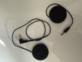
1782494819864.png


The reason for the user using a single speaker is 1. safety, so they have some chance of communicating other people 2. volume, as a single speaker will be louder than driving both speakers (the amp is mono anyway) 3. redundancy, as the other ear usually has another audible device to indicate altitude

Of course, the user could decide to use both speakers, but they do this at their own risk.

Shorting the ring and tip solves this problem, UNLESS a mono jack is inserted which would short the amp output. So it solves the problem for a stereo jack but breaks it for a mono jack.

The DPDT switch in your circuit was what I was hoping to do, but when I looked at DIP switches the current rating is only a few hundred mA which is too low for the amp.

I have very very little space, even a DIP switch will be very difficult to fit. So a DPDT switch with a higher current rating is likely to be too large.

I dont think the capacitors and resistors in your circuit would work, because the output of the amp is not analogue. Its a class D amp, so the output is PWM.
 

AnalogKid

Joined Aug 1, 2013
12,183
I dont think the capacitors and resistors in your circuit would work, because the output of the amp is not analogue. Its a class D amp, so the output is PWM.
That is exactly why the caps and resistors are needed.

The average value of each output is +2.5 Vdc, and the PWM signal swings +/-2.5 V around this, from 0 V to 5 V (ish). This is not a problem when the speaker is connected to the two outputs, because the DC difference between them is 0 V. When driving a single speaker that is grounded, you now have a constant 2.5 V DC across the speaker plus the PWM component.

The capacitors remove the DC component from the PWM waveform going to a speaker. The resistors prevent the average value of an unused output from floating up to 2.5 V (as the capacitor is discharged by its own leakage current), which could produce a dangerously loud POP when connected.

ak
 

boostbuck

Joined Oct 5, 2017
1,056
Since you are modifying the stereo jack to disable one or the other speaker thus creating a helmet with only one side active, surely you can just cut the jack off and wire a mono jack in its place, connecting either the right or left wire.

Alternatively, make a short adapter cable with mono plug and a stereo socket. The stereo socket has either (right or left) ring or tip wire connected. Then the adapter can be used with standard two-speaker helmets without modification.
 
Last edited:

Thread Starter

freeflyer

Joined Sep 9, 2016
169
Since you are modifying the stereo jack to disable one or the other speaker thus creating a helmet with only one side active, surely you can just cut the jack off and wire a mono jack in its place, connecting either the right or left wire.

Alternatively, make a short adapter cable with mono plug and a stereo socket. The stereo socket has either (right or left) ring or tip wire connected. Then the adapter can be used with standard two-speaker helmets without modification.
Yes I can do all this myself, but if I were to start selling these devices then most people would not be able to do this and its not very professional. Cutting a wire on a pair of speakers is not very professional either, but I don't see any other option other than asking the speaker manufacturer to make custom speaker which would cost a fortune and due to low volumes they would not be interested.
 

boostbuck

Joined Oct 5, 2017
1,056
Well, maybe you supply your amp with two adapter cables, one wired for left and one for right. The user picks the one that suits. Since the amp itself would have a mono socket a user with a mono headset would plug directly in.
 

Thread Starter

freeflyer

Joined Sep 9, 2016
169
Well, maybe you supply your amp with two adapter cables, one wired for left and one for right. The user picks the one that suits. Since the amp itself would have a mono socket a user with a mono headset would plug directly in.
That would depend on cost as the adapter cables would have to be custom made
 

Thread Starter

freeflyer

Joined Sep 9, 2016
169
If your speaker is 63 Ohms as stated, then the maximum speaker current is only about 80mA with a 5V supply to the amp.
Interesting, so a small DIP switch could be an option then.
I need to understand the PWM more. When I briefly looked into class d amps I read that another reason they are more efficient is because it effectively doubles the voltage. So with a 5V supply for the amp the speaker would actually see 10V, because the h-bridge is always changing polarity so the voltage would always be changing between +5V and -5V. ?

Another helmet speaker I have is 32 ohms, so I also need to account for lower resistances.
 

AnalogKid

Joined Aug 1, 2013
12,183
In its intended operation, the MAX device drives a BTL - Bridge-Tied Load.

https://en.wikipedia.org/wiki/Bridged_and_paralleled_amplifiers#Bridged_amplifier

The idea here is to effectively double the peak-to-peak voltage swing seen by the load, which increases the max power to the load by a factor of 4. This has nothing to do with PWM versus linear amplification. In both cases, doubling the voltage quadruples the power. This comes from a permutation of Watt's Law, P = E^2 / R.

It also has nothing to do with efficiency. Higher efficiency comes from the amplifier (actually each of the two internal amplifiers) being a switching topology rather than linear.

ak
 

ThePanMan

Joined Mar 13, 2020
937
I don't understand why you can't just build a patch cord; one that plugs into the existing plug with connections to whatever headphones you like.
 

Thread Starter

freeflyer

Joined Sep 9, 2016
169
I don't understand why you can't just build a patch cord; one that plugs into the existing plug with connections to whatever headphones you like.
I can, but if i sell hundreds of these devices I would have to pay a company to make all these custom patch cords which will soon add up in cost
 

Thread Starter

freeflyer

Joined Sep 9, 2016
169
hi free,
What is your expected manufacturing/selling costs and quantity?
E
Thats I good question and I dont have a valid answer and not sure how to find out.

Its a prototype at the moment and I have not advertised the device, there are competitors on the market although mine has a unique feature that others do not.

I had 5 blank boards and 1 assembled board made by PCB Way which cost £200. There's the additional cost of the helmet speakers (a decent quality costs ~£90 for a pair), the battery (£6) and the enclosure (3D printed)

With economies of scale, this will reduce but it obviously depends on quantities. And to make things more difficult some of the components (Texas Instruments buck regulators and inductors)are out of stock until the end of the year.

Skydiving is a niche market, there is around 6,400 skydivers in the UK and around 100,000 world wide.
 

Thread Starter

freeflyer

Joined Sep 9, 2016
169
In its intended operation, the MAX device drives a BTL - Bridge-Tied Load.

https://en.wikipedia.org/wiki/Bridged_and_paralleled_amplifiers#Bridged_amplifier

The idea here is to effectively double the peak-to-peak voltage swing seen by the load, which increases the max power to the load by a factor of 4. This has nothing to do with PWM versus linear amplification. In both cases, doubling the voltage quadruples the power. This comes from a permutation of Watt's Law, P = E^2 / R.

It also has nothing to do with efficiency. Higher efficiency comes from the amplifier (actually each of the two internal amplifiers) being a switching topology rather than linear.

ak
I took an oscilloscope capture of the amplifier output but it makes no sense to me, the waveform is the same at each speaker terminal...

1782824751082.png


Each probe was connected to one side of the speaker and the ground of the probe was conenected to battery negative.
 

MisterBill2

Joined Jan 23, 2018
27,752
OF COURSE! With no signal output the differential output is zero, exactly what we see. It will be quite different with a sine wave output AND the intended load connected. The amplifier is obviously a high efficiency type.
Without any load OR an output filter, the output will be a high frequency PWM signal, full of high frequency harmonics and probably able to radiate the signal that will interfere with nearby electronics.
Do you have any application circuit information from the manufacturer or the supplier??
 

Thread Starter

freeflyer

Joined Sep 9, 2016
169
OF COURSE! With no signal output the differential output is zero, exactly what we see. It will be quite different with a sine wave output AND the intended load connected. The amplifier is obviously a high efficiency type.
Without any load OR an output filter, the output will be a high frequency PWM signal, full of high frequency harmonics and probably able to radiate the signal that will interfere with nearby electronics.
Do you have any application circuit information from the manufacturer or the supplier??
That’s why I’m confused though, there was audio playing and the speaker was connected. I even tried a math subtraction to display the difference between both channels but the difference was mostly zero.

An application circuit is shown in the datasheet

https://www.analog.com/media/en/technical-documentation/data-sheets/max98357a-max98357b.pdf
 

MisterBill2

Joined Jan 23, 2018
27,752
That’s why I’m confused though, there was audio playing and the speaker was connected. I even tried a math subtraction to display the difference between both channels but the difference was mostly zero.

An application circuit is shown in the datasheet

https://www.analog.com/media/en/technical-documentation/data-sheets/max98357a-max98357b.pdf
Can you be more specific about "there was audio playing" ?? What was connected to the input?? Many audio systems can detect AM radio broadcast signals and produce an output. That is quite common. Sometimes it is a serious problem.
 
Top