Solenoid valve control with relays

Thread Starter

leonhart88

Joined Feb 23, 2007
118
Hi everyone,

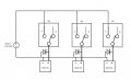
I am using Solenoid pinch valves (http://www.clarksol.com/html/prodspecsPK_Valve.cfm) to control the flow of fluid in a device I am making. I have 6 of these valves and I need a way to turn on/off each valve via a LabView program.

Each solenoid valve runs off 12VDC and takes roughly 1A of current (10-13W power). I have a single 12VDC, 5A power supply that will be used to power the valves.

I have been looking at these two relay controllers. One is much cheaper than the other, and I am not sure why. The more expensive one looks higher quality, with more capabilities (which I don't really need). Here are the links:
http://hobbykits4u.net/rs232-serial-relay-control-board-p-28.html
http://www.easydaq.biz/PagesUSB/USB8PRSRFRAME.htm

One question I have is about snubber circuits, or protection from solenoid back EMF. According to one of the manufacturers (hobbykits4u), I would need some sort of back EMF protection. I don't really know too much about this, and I have no one to ask at work. Some of the techs I asked said they have never needed to use snubber circuits, or protection for their solenoid valves. At first I thought it was because they were using manual switches, which I assume would not need any protection. But they told me they have used relays as well.

Could someone please explain if I need back EMF protection and why? If someone could also suggest which relay controller is better, I would appreciate it. To be honest, I think the one from hobbykits4u suits my needs perfectly and is a good price. But I am a bit skeptical of the quality compared to the more expensive one. Thank you for any help you can give me!

Thanks,
Philip
 

timrobbins

Joined Aug 29, 2009
318
The solenoid is, as the name suggests, and inductor. Whenever you switch off a current that is passing through an inductor you generate a voltage across the inductor that is giverned by the equation V = L di/dt. Depending on the circumstances of the circuit, that 'back emf' can appear across other circuit devices at sufficient levels to damage them. The simplest method to alleviate the back emf in DC switched circuits is to put a diode across the solenoid coil (polarised to only conduct when the DC current in the coil is switched off).

Ciao, Tim
 

Thread Starter

leonhart88

Joined Feb 23, 2007
118
Thanks for the reply Tim. I have been reading articles online and I think I understand a bit better.

Also, if I look at the equation V = L*di/dt, does that mean during power on, there is a large positive voltage spike? Does this have the potential to damage anything? I am just curious on this one...

I am still confused a bit about the back EMF damaging other circuitry. I am reading this website: http://www.progeny.co.uk/Back-EMF-Suppression.aspx, and I understand the concept of the solenoid storing energy and then releasing it. However, what can the EMF damage in the example given on the website? It seems like the solenoid acts as a voltage source, but there isn't a complete circuit here so I am confused.

I have attached a drawing of my setup for one relay. I am either switching ON (completing the circuit to a 12VDC power supply), or I am breaking the connection and turning the valve OFF. I have no other circuitry connected. The relay itself is connected to other circuitry (using one of the relay controllers I previously mentioned). If the solenoid acts as a voltage source, then current would run through the OFF path. But I have nothing connected to the OFF path, so what would happen? Where is the potential for circuit damage?

I appreciate your help and I apologize if I am misunderstanding something...I am more specialized in computer engineering than electronics.

Thanks,
Philip
 

Attachments

whale

Joined Dec 21, 2008
110
Hello leonhart88,

according to your circuit, you are connecting relay to switch on/off the solenoid. solenoid is nothing but an inductor. so when you activate your relay to switch on the valve , at starting period no back emf will be generated in the solenoid ( because the back emf is created only after magnetizing the solenoid coil ie, after applying voltage across solenoids ) and the current flow will be at its peak level since there is no opposing back emf and also the resistance of solenoid coil will be very low. After a fraction of micro second back emf will be produced by the solenoid coil and the forward current flow will be limited by back emf , thus circuit attains its stable condition.
now you think about the period of time between after applying forward voltage and before development of back emf. this period will be a very short duration of time but the current forward current level will be at peak due to its low resistance path. your circuit can be assumed to be at short circuit during this period of time. due to the short circuit nature of your circuit during that specific span of time, the voltage developed by your power source will be lower than the actual voltage expected(because the power level will be maintained constant always ; when current level is increased the voltage will be decreased to maintain power level and vice verse). thus voltage fluctuations will affect the circuits connected in parallel with your power source. in order to avoid this problem snubber circuits are developed which will interrupt the peak current produced during short period of time and the supply voltage will be maintained constant.
 

Thread Starter

leonhart88

Joined Feb 23, 2007
118
Thanks for the reply whale.

I'm pretty confused now...I pretty much want to control valves like shown in this attached picture.

I thought I could just connect the + and - directly, like I would do with manual toggle switches.

To protect each relay from back EMF, wouldn't I just use a diode across each solenoid valve?
 

Attachments

Jaguarjoe

Joined Apr 7, 2010
767
To make it perfect, you'll need six diodes. Three across the solenoid coils as discussed here, and three across the relay coils to protect the circuit that drives those relays. You will be back-emf free!
 

Teri

Joined Apr 3, 2009
12
Also, if I look at the equation V = L*di/dt, does that mean during power on, there is a large positive voltage spike?
No. When the circuit is activated, the voltage is set by your power supply at 12 volts. The current through the circuit is at first zero, then increases at a rate (di/dt) governed by the solenoid inductance and resistance. With practical solenoid inductance values, the current reaches maximum (governed only by supply voltage and resistance) within a very few milliseconds.

It's a different story when the circuit is opened suddenly. With a one-amp solenoid the current goes from 1 amp to zero amps in zero seconds, so di/dt = 1/0. In theory, the voltage would become infinite; in practical circuits there are losses that prevent it. But the voltage can be hundreds of volts. This characteristic is used to advantage in high-voltage flyback power supplies. But, it can create a high-temperature plasma (ionized air) between relay contacts, or destroy low-voltage driver transistors or ICs.

If a circuit with a diode "snubber" is opened, the resulting voltage is applied to the now forward-conducting diode which causes current flow to continue for a few milliseconds, limited by the resistance of the solenoid and the colapsing magnetic field, so that di/dt is a very small value.

Probably more than you want to know:
"Snubbers" can be diodes or they can be a series-connected capacitor and resistor of the proper values. C-R snubbers are mostly used in high-speed circuits or on AC circuits where a diode snubber can't be used because it would short 1/2 of the AC cycle.

Comparison of the two boards:
The Hobbykits boards looks like a good deal as long as your computer has an RS-232 port. I don't see a relay contact rating but the relays should handle 12v 1A solenoids ok as long as you use snubber diodes.
The Easydac board also looks good and would be the logical choice if your computer doesn't have an RS-232 port. Much of the price difference is because of the extra needed interface for the USB port.

The bottom line:

If it were up to me, my choice of boards would be the hobbykits if my computer had an RS-232 port, otherwise it would be the Easydac board. (You could use the hobbykits board with USB adapter, but that would be a kludge that would cost about the same as the Easydac board.)

Because the spacing of the relay contacts is likely small, it would be easy to burn the contacts with a plasma (IIRC, it doesn't take much voltage to start an air plasma, and only 10 volts to maintain it.) And, diodes are cheap, so I would add one accross each solenoid (cathode toward positive supply side).

Hope this helps, and good luck on your project,

Teri
 

Attachments

Thread Starter

leonhart88

Joined Feb 23, 2007
118
Thanks JaguarJoe.

I will be using this relay controller http://hobbykits4u.net/rs232-serial-...oard-p-28.html, which I believe already has diodes which protect the circuit from the relay coils. So according to my schematic, I would only need 3 diodes across each solenoid right?

Is there any specific calculations I have to do to pick a good diode? Also, would the diode cause the valve to turn off slowly (how slow)?

Do people worry about back EMF when they use manual toggle switches as well?

I have attached a picture of the schematic with diodes, please let me know if they are in the right direction. Thanks for the help!

Thanks,
Philip
 

Attachments

Thread Starter

leonhart88

Joined Feb 23, 2007
118
No. When the circuit is activated, the voltage is set by your power supply at 12 volts. The current through the circuit is at first zero, then increases at a rate (di/dt) governed by the solenoid inductance and resistance. With practical solenoid inductance values, the current reaches maximum (governed only by supply voltage and resistance) within a very few milliseconds.

It's a different story when the circuit is opened suddenly. With a one-amp solenoid the current goes from 1 amp to zero amps in zero seconds, so di/dt = 1/0. In theory, the voltage would become infinite; in practical circuits there are losses that prevent it. But the voltage can be hundreds of volts. This characteristic is used to advantage in high-voltage flyback power supplies. But, it can create a high-temperature plasma (ionized air) between relay contacts, or destroy low-voltage driver transistors or ICs.
Ah I see, thank you for the explanation, it makes a lot of sense now!

If it were up to me, my choice of boards would be the hobbykits if my computer had an RS-232 port, otherwise it would be the Easydac board. (You could use the hobbykits board with USB adapter, but that would be a kludge that would cost about the same as the Easydac board.)
Thanks for your input! I was actually going to purchase the hobbykits and a USB to serial (since we are using a laptop). A serial to USB costs ~20$ here, so I thought it would still be cheaper. However, I should look at the costs again, as the Easydac board looks higher quality anyway.

Because the spacing of the relay contacts is likely small, it would be easy to burn the contacts with a plasma (IIRC, it doesn't take much voltage to start an air plasma, and only 10 volts to maintain it.) And, diodes are cheap, so I would add one across each solenoid (cathode toward positive supply side).
So what you're saying is that...even though there are no circuits connected to the OFF path that can be damaged by the back EMF, the relay contacts themselves can be damaged. Is this problem also present in manual toggle switches?

Hope this helps, and good luck on your project
Yes, it will definitely help, thanks Teri!

*Edit: How would I go about picking a diode? Are there any voltage/current calculations I need to do?

Thanks,
Philip
 

Jaguarjoe

Joined Apr 7, 2010
767
A diode across a solenoid will slow it down when it de-energises. We're only talking miliseconds though, probably not enough to worry about. But if this will cause a problem you can place a zener diode across the contacts of the relay and skip the snubber diode across the coil. The zener will limit the back emf voltage across the relay contacts thus limiting the spark across those contacts.

Many people use 1N4001 diodes for snubbers, some like 1N4148's. You will be fine with either one.
 

Thread Starter

leonhart88

Joined Feb 23, 2007
118
I have some IN4007s in my toolbox. I assume an IN4007 would work, since they are the same (except 4007 has a higher voltage tolerance).

Thanks a lot guys, I really appreciate it! Will let you know if I run into any other problems.

Thanks,
Philip
 

kingdano

Joined Apr 14, 2010
377
you should reconsider your voltage supply

6 solenoids drawing 1A each is 6A - you have 5A available.

i didnt read the thread in detail, but that jumped out at me.

will all 6 not be active at the same time?

you should have at least 8A of available current IMO
 

Thread Starter

leonhart88

Joined Feb 23, 2007
118
you should reconsider your voltage supply

6 solenoids drawing 1A each is 6A - you have 5A available.

i didnt read the thread in detail, but that jumped out at me.

will all 6 not be active at the same time?

you should have at least 8A of available current IMO
Thanks for the reply kingdano. The valves are normally closed. Usually only 2 valves will be on/open at one time. We may have all valves open for very short periods of time in order to remove tubing from the pinch valves. Since the valves don't need to be fully open at this time (it's OK if they are drawing less than 1A), I thought it may be OK. Is this a bad idea?
 

kingdano

Joined Apr 14, 2010
377
Thanks for the reply kingdano. The valves are normally closed. Usually only 2 valves will be on/open at one time. We may have all valves open for very short periods of time in order to remove tubing from the pinch valves. Since the valves don't need to be fully open at this time (it's OK if they are drawing less than 1A), I thought it may be OK. Is this a bad idea?

short answer? yes.


general design rule of thumb is always to allow overhead for losses and tolerances.

you wouldnt want to operate a 1A circuit with a 1A power supply - you would be asking for trouble.

in this case - even though you may only request all valves to be energized together for short times, you could still cause voltage sag or power-supply shutdown (depending on how its designed - safety features etc) if you over-current the supply.

my general rule of thumb is to do the math for the big pieces of the system - the big power draws - look at some quiescent current numbers and then add a 50% overhead to the supply.

i am very conservative with these types of things, including capacitor voltage ratings and any ab-max rating on a datasheet - i try to avoid if at all possible.

just my rule of thumb.

go with a beefier 12V - 8-10A supply and then you can be almost positive if the solenoids are acting funny, or if your circuit is, that its not because you're out of power.
 

Thread Starter

leonhart88

Joined Feb 23, 2007
118
Thanks kingdano...I was actually worried about this for a while, but thought it would be OK.

I may be able to get around ordering a beefier power supply if the valves I ordered have a manual release button. I know some solenoid pinch valves have them, but I have not checked.

However, I like the idea of pressing one button to release all the valves/tubing so I will look out for a suitable power supply. Probably something like this: http://search.digikey.com/scripts/DkSearch/dksus.dll?Detail&name=237-1304-ND.

Thanks,
Philip
 

kingdano

Joined Apr 14, 2010
377
you should do some more hunting for a power supply

start with

www.mpja.com

they have lower priced supplies, digikey - while a great place to find parts - does not always offer the best prices - especially in low quantities.

you can probably get one for 25-35 USD
 

kingdano

Joined Apr 14, 2010
377
not a problem

the majority of the posters here are very much into the art behind design so we enjoy digging into problems.

good luck with your project!
 
Top