Solar grid inverter - lightning damage?

Thread Starter

Rsanderhoff

Joined Mar 4, 2018
11
Hi all

I hope someone can help me a bit forward here. I’m the owner of some solar panels which are connected to our 230V 50Hz grid through an Inverter. It’s a Kostal Piko 4.2kW from 2013.

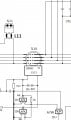
Last summer it suddenly started to give error messages and make shutdowns as soon as the power went slightly up. See picture “inverter_question3”. It’s a bit unknown if there were thunderstorms in the period of time where the fault occurred.

The inverter makes weird sounds before the fault occurs. You can hear it on this video:


It gives these two error codes some time several times a day:

903: system fault – see it here:

241: Over current AC-side.

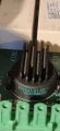
I thought the IGBT might were causing the faults, but from my simple measurements with my digital multimeter this does not seem to be the case. My plan is to replace all the 6 IGBT´s anyways as I had to cut some of the legs during disassembly.

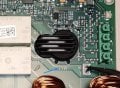
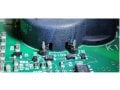
From Visual inspection there is only one place where a component looks a bit burned. See picture inverter_question2. But I don’t know what this component does and if this is an issue at all.

My question is now:

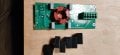
  • Does anyone have any ideas of what could cause these faults? Relays-Capacitors-IGBT’s anything? I have attached a picture of the AC-board.
Best regards Rasmus
 

Attachments

sagor

Joined Mar 10, 2019
903
First, I would look up in any manual what the 903 error means. Contact the vendor if possible.
Lightning can damage things, even without a direct hit. If something hit your outside powerline, it could have fed back into your inverter.
 

Thread Starter

Rsanderhoff

Joined Mar 4, 2018
11
Hi Sagor.

Thanks for your reply.

I get two different error codes.

903 system fault.
241 overcurrent AC-side.

I have already looked in the manual, and this only have the headline, and to call the support. At the support they are helpful, but primerly they just want me to buy a new inverter costing 2k EUR. They basically don't want me to do the repair myself. If I can fix it by identifying and replacing the damaged components, its worth a try.

I have seen some people have succes in replacing the igbt's and the white safety relays. But I still haven't tested the safety relays because I cannot figure out which pins are the coil pins.

BR. Rasmus
 

sagor

Joined Mar 10, 2019
903
They probably don't want you to repair it because if something goes wrong, you could be feeding wrong voltages into the grid, or even worse, the grid comes in and starts some kind of fire in your inverter, burning down your house. Manufacturer does not want to be liable for that.
In other words, repair at your own risk, and your insurance will not cover your if something goes wrong. Your choice...
 

Thread Starter

Rsanderhoff

Joined Mar 4, 2018
11
Hi Alec-t, thanks for your answer.
They don't have any marks. It's a relay from DOLD. I did figure out which pins were the coil pins on the safety relays. And they seem to work fine. So I guess they are not the issue.

Anyone having any idea of what component is is I'm asking about in first picture? The black round thing that is looking a bit burned? I cannot find it on Google search.

I have attached another picture of the component with text here.
 

Attachments

Alec_t

Joined Sep 17, 2013
14,280
That mystery component seems to be designated K18x? I've seen 'K' used to designate relays/contactors elsewhere, and it looks to have magnet wire entering/exiting it in your 'question2 pic. Can you trace if it connects to the L1,L2,L3 and N lines? It's clearly designed to run hot, judging by the heat-sink fins on top. If it is a relay/contactor the noise in the video could be contact chatter or arcing.
 

Thread Starter

Rsanderhoff

Joined Mar 4, 2018
11
You are right about the K's means s relays concactors. But thats for the safety relays on the other side of the K's.
This component is mentioned as M41 on the PCB. And yes. It's connected directly to N, L1, Ł2 and L3. Right between the filter pcb and the safety relays.

You are also right that there is small cobber strings going into the side of this component, maybe a coil?. I have actually found a schematic of this board. It must be the component called X10. But I still don't know what it is and thereby where to buy a new.
 

Attachments

debe

Joined Sep 21, 2010
1,389
Id say a current transformer the fins are to provide insolation barrier betwean each wire. Check for continuity on the thin wire conections, it may not be faulty. Ive replaced plenty of isolation relays in grid tie inverters as the contacts burn. They usualy flag AC problem. Also dry solder joints are common on the relays & the switching MOSFETS. Have also replaced a switching MOSFET with a hole blown in it. Surprised you actualy found a circuit.
 

Alec_t

Joined Sep 17, 2013
14,280
Current transformer makes perfect sense. Its assumed secondary coil terminals go to the inputs of a TS3702 dual comparator. The single-turn primaries would likely get pretty hot; hence the fins.
 

Thread Starter

Rsanderhoff

Joined Mar 4, 2018
11
Hi debe and AlbertHall- thanks for your answers.

Thanks for your suggestions. Now I have been searching for hours without finding anything looking like this component. When looking closer at this component I can see that it looks like its just transfering N,L1,L2 & L3 from one point at the PCB to another. And then the two really small pins in the side is a thin coil around the N,L1,L2 & L3. Maybe a sensor or some kind of current detector. I have confirmed that the coil is still intact, and I believe I have to conclude that this might not be the component causing the issue.

Instead my plan is now to replace the components as you describe debe the following:

2pcs safety relays. I can hear them clicking but I havent confirmed that they actually close as they should with good contact. Im a bit afraid if I damage some surrounding components if I apply 12V to the coil to long. Maybe the best would actually be to dismount the relays to test them properly?

I still havent found the relays anywhere, so now I have written to my local shop to ask if they can get them to me.
Brand: DOLD
OA 5621.04 / 3781W1 / 61 picture attached.


6pcs IGBT transistors ordered already from my local shop. https://uk.rs-online.com/web/p/igbts/8268223?sra=pstk
Im going to replace them even thought they all seem to work when testing with this method:

Again, thanks for your answers, and your help.

BR Rasmus
 

Attachments

debe

Joined Sep 21, 2010
1,389
One picture is dry joints on relay pins & one was burnt off. Other pic is the only relays i could get, & they were from China & i purchase 10 so i had spares As you can see they are mounted off board as the pin spacing was different. Grid tie relays are very hard to source.GTIE.1.JPGGTIE.2.JPGGTIE.3.JPG
 

Thread Starter

Rsanderhoff

Joined Mar 4, 2018
11
Hi debe. Thanks for your input.

It's a good point to also look for dry joints. I will see if anything seems to need resoldering. Last night I checked the DC relays, and they seem to work fine. Left is still to see if the AC safety relays works.

Actually I had maybe hoped that something looked burned, so I was obvious what needed replacement. But it's not in this case.

Currently it's still the plan to replace the igbt's and also the AC relays if my dealer can find them somewhere.
 

Thread Starter

Rsanderhoff

Joined Mar 4, 2018
11
Short update from me. While waiting for the igbt's arriving, I started to look at the capacitors on my AC side. To be sure to get the right values I dismounted a few, and it quickly showed that several of them already retired. I guess this also be the cause of all the faults I received.
Especially the capacitors that were connected to L1 were as low as 37% of their original capacitance. And that might also be the cause of the difference in the output voltage you can see in the attached screenshot. Now I'm going the check the remaining capacitors, and replace the majority of them.
 

Attachments

musiklab

Joined Jul 20, 2014
5
Hi, Rsanderhoff, I am looking at a similar problem with a LUXRA brand = Kostal Piko5.5 . This is very similar to yours.
I would be grateful to know if you fixed your inverter , and how . Mine runs perfect with one string of panels attached reducing max power to 3kW , connecting a second string produces 5kW AC upload at about 7.5+ AC Amps , this power soon makes it emit a quiet "zzzz sizzling/ frying sound" from around the mains out filter, ( on top of what I think is the inverter frequency around 600Hz) , and then all turns off, "malfunction m, or grid failure", repeating this every 5 minutes.
I believe it may be the DOLD OA relays overheating, because of pitting contacts , after 8 years service. or something else . I am looking for new replacement safety relays, these are crucial to safety. help appreciated !
the 2.2uF capacitors are shunting off a bit of current, so a lower value should show higher voltage, but they are definitely worth changing when deteriorating. Polypropylene 310V X rated or better with the correct pin pitch .
Kostal offers me a complete replacement refurb unit for ~500€ , or Secondsolar repairs or sells used refurbs at around the same cost. https://www.secondsol.com/en/anzeige/24977/inverter/string/kostal/piko-5-5-dcs
Thanks for all the info so far, I´d be pleased to hear how it went. best, M.
 
Top