Facebook
 Google
 GitHub
 Linkedin
Hello everyone, hope someone can offer advice.
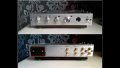
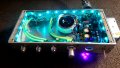
I have built a hifi preamp, ESP P97 to be exact and very good it is too. The preamp itself runs from a dual linear power supply and there are no issues.
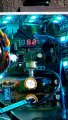
However, I have also placed a SMPS into the case to power a 5v LED strip and although it works (LED's power on), I have a massive, and I mean massive, buzz through the preamp.
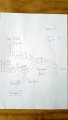
The incoming mains is via chassis IEC which then goes to a switch, then a terminal block where I have connected both the linear power supply for the pre amp and also the SMPS for the LED strip together.
Maybe something simple I am doing wrong, maybe you cannot do this, but the way I have wired them together is not any different than having them both connected, albeit individually, into a mains extension block.
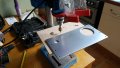
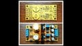
Any ideas would be greatly appreciated. A couple of photos of the preamp plus a sketch of the mains wiring.
Regards
Adam.
I have built a hifi preamp, ESP P97 to be exact and very good it is too. The preamp itself runs from a dual linear power supply and there are no issues.
However, I have also placed a SMPS into the case to power a 5v LED strip and although it works (LED's power on), I have a massive, and I mean massive, buzz through the preamp.
The incoming mains is via chassis IEC which then goes to a switch, then a terminal block where I have connected both the linear power supply for the pre amp and also the SMPS for the LED strip together.
Maybe something simple I am doing wrong, maybe you cannot do this, but the way I have wired them together is not any different than having them both connected, albeit individually, into a mains extension block.
Any ideas would be greatly appreciated. A couple of photos of the preamp plus a sketch of the mains wiring.
Regards
Adam.
Attachments
-
 5.9 MB Views: 31
 -
 5 MB Views: 30
 -
 4.8 MB Views: 26