SMD transistor power dissipation

Thread Starter

drvlas

Joined Oct 16, 2015
28
Hi everyone!

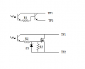
I develop a simple MCU based board with 8 digital inputs and 8 digital outputs. Every channel is opto decoupled.
The outputs are classical: MCU pin + Optocoupler with Phototransistor. I want to add a transistor as an output stage to optocoupler. It have to switch up to 400 mA DC and to hold 60 V DC. Minimal hFE = 100. Nothing extra ordinary, you see.
Since I have a zero experience in modern transistors use, I am in doubts even about the case needed. The general purpose SMD transistors in SOT-23 (or similar) seem to be OK. The BCV71 is an example. But when I think about 350 mW being dissipated by such a micro case... Will it be as hot as a pan?
Maybe it's better to use TO-92 case transistors? I saw some boards of similar functionality with rows of TO-220 transistors... But the hFE is much worse, as a rule. And the price is higher.
So my questions are:

1) Can you tell me, is it okay to use that tiny SOT-23 in my case?
2) Maybe someone will propose popular models of transistors to use (SOT-23 or TO-92 or what you consider relevant). To narrow my search :)

Best regards,
 

#12

Joined Nov 30, 2010
18,224
One problem here is that gain goes down as Vce approaches zero. The BCX56-16 has a gain of 100 with 2 volts collector to emitter. That's 0.8 watts. That seems OK, but can you afford 2 volts collector to emitter?

A mosfet seems a better candidate because they have gotten so much better in the last 10 years. Let's talk about how much gate (base) drive voltage you have available.
 

Thread Starter

drvlas

Joined Oct 16, 2015
28
BCX56 is good, thanks! "Power pack" :)

As I see it, gain 100 @ 2V is just a mark. We don't know what exactly happens at 1V.
About MOSFET. The output circuit is passive. There is 24V voltage which has to be closed to minimal (saturation) level. No 2.8V.
 

#12

Joined Nov 30, 2010
18,224
Connect pin 4 of the opto-isolator to about 3.5 to 4 volts.
60 volts is more than 4 volts, so I think you can get what you want on-board.
Besides, mosfet gates require very little current if you aren't doing high frequency switching.
This mosfet will survive up to 20 volts on its gate, so you have plenty of room for fudge factors.

I'm assuming pin 2 of the mosfet gets grounded.
 

Thread Starter

drvlas

Joined Oct 16, 2015
28
I design the board to work with several parts of a system. Some have 24V power, some -24V, some may be 12V-driven... Theoretically every channel may be of different power source. So I need to have 2 wires to my switch and no other links.
I'd like to use MOSFETs, of course. I use 2N7002 in other designs - and like it.
 

#12

Joined Nov 30, 2010
18,224
I need to have 2 wires to my switch and no other links.
That doesn't make sense. If you use an NPN, it must have base current, and there remains a collector and an emitter.
If you use a mosfet, it must have gate voltage, and there remains a source and a drain.
They are basically the same thing except the NPN needs current and the mosfet needs voltage. Both of them must have their emitter (source) connected to the drive voltage circuit somewhere.
I would need a drawing to figure out why a mosfet won't work for this circuit.
 

Thread Starter

drvlas

Joined Oct 16, 2015
28
Thanks to #12!

So the main question is answered in a way: use more power-dissipating SMD cases. I will search BCX56-like transistors, maybe with the better hFE.
Maybe some sort of ZTX694B (super-beta?)... No one proposes trough hole? Or smd super-beta?
 

AlbertHall

Joined Jun 4, 2014
12,625
I think it doesn't need additional source to feed base.
The transistor in the opto-coupler will need some voltage to conduct enough current to turn on the output transistor (you don't say what the coupler is so we can't look that up). That voltage plus the base emitter voltage of the output transistor gives the emitter-collector voltage of the output transistor (that transistor will not be saturated) and so the dissipation will be a good bit higher than if the transistor was saturated.
 

Thread Starter

drvlas

Joined Oct 16, 2015
28
the dissipation will be a good bit higher than if the transistor was saturated.
Yes, Sir! As I estimate, ab. 1.5 V is the minimal voltage between TP1 and TP2. That makes 600 mW @ 400 mA.
BCX56 can hold it, if with mounting pad of 1x1 cm. But maybe some TO-92 transistor will be more suitable?
 

#12

Joined Nov 30, 2010
18,224
I don't see the problem.
The voltage source for the opto comes in TP1
In the NPN circuit, R1 protects the base from excess current.
In the mosfet circuit, R2 protects the Zener from excess current, Z1 protects the gate from excess voltage, and R3 drains the gate voltage to turn the mosfet off.
 

Attachments

#12

Joined Nov 30, 2010
18,224
I see your point.
If you can't connect to pin4 of the opto with the voltage that runs the opto at its input side, you will run out of gate voltage.
 

Thread Starter

drvlas

Joined Oct 16, 2015
28
Okay, fellows. I cleared the topic a little. Thank you!
Now I have to make a decision in a completely different domain: economics. The MOSFET optocoupler G3VM-61G1 is very good, it suits everything. I used it OK some time ago. The only thing to think is $2.14...$2.25 for a piece. But no transistor, no resistor, no power troubles and less than 0,8 V open voltage. Uhm...
Screenshot from 2016-07-11 14:38:43.png

P.S. And bipolar output, as a bonus :)
 

OBW0549

Joined Mar 2, 2015
3,566
Okay, fellows. I cleared the topic a little. Thank you!
Now I have to make a decision in a completely different domain: economics. The MOSFET optocoupler G3VM-61G1 is very good, it suits everything. I used it OK some time ago. The only thing to think is $2.14...$2.25 for a piece. But no transistor, no resistor, no power troubles and less than 0,8 V open voltage.

P.S. And bipolar output, as a bonus :)
I vote for the MOSFET optocoupler, unless cost is an over-riding consideration. It's simpler, takes up less circuit board area, and the symmetrical output is indeed a plus since it removes any polarity requirements from your output connections.
 

#12

Joined Nov 30, 2010
18,224
It sure took me a long time to figure out the output had to be 2 wires only, and there is no common ground.
It almost seems like a job for a relay.
 
Top