 Facebook
 Google
 GitHub
 Linkedin
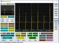
Hello This is the sim and the waveform I could sim was a nice sinus. On real PCB the oscillation are no sinuses but pulses.
Th signal was taken at the "OUT". Voltages indicated on the bitscope screen are to be multiplied by 10. (becomes 5V/div)
Also the frequency is 61KHZ instead of 400Khz.
Any ideas?
PS The L1-L2 was made of (0.6mm diam wire) windings on a paper center of about 8mm as described in the .ASC , without a core and on each other. Inserting an iron core diminished the amplitude by 1/3.
Attachments
-
 99.6 KB Views: 10
 -
3.5 KB Views: 4
-
 132.5 KB Views: 12
Last edited:


