 Facebook
 Google
 GitHub
 Linkedin
Sorry for my limited knowledge on these motors. I had a security gate that would no longer open or close. Took the motor out because when asked to open or close the gate it would only sit and humm. Tested the run capacitor and it was bad and bulging. Now the gate will happily run and CLOSE the gate but when asked to open the gate it just sits and humms, I can assist by hand spinning to help it get going but it will not open on it's own. I am not sure where to go. Owner did say that this past winter after a snow storm the gate tried to open at the normal time but got stuck on a snow pile and just sat there buzzing until he turned power off and manually opened the gate. Here is a link to a video I took of it trying to run in the "open gate" direction. While it does appear to start here it has zero power to get the gate opening when the belt is on.
Attachments
-
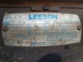 408.7 KB Views: 6


