Single antenna feeding two receivers...

Thread Starter

Externet

Joined Nov 29, 2005
2,217
Hi.
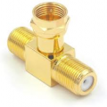
The output of a plain antenna fed to 2 receivers with a 'Y' or 'T' connector; what losses are expected per branch ? What changes are expected in impedances ?
1636040921324.png1636040947465.png


How different are compared to a 'splitter' ? :

1636040332015.png
 

Attachments

LowQCab

Joined Nov 6, 2012
4,067
It's almost impossible to guess how many different problems You could create.
Even having 2 separate Antennas mounted close to each other will have odd, adverse effects.
.
.
.
 

bertus

Joined Apr 5, 2008
22,276
Hello,

What will be the frequency range that goes though the splitter?
The Y you show in the openings post looks like to be used for car radio and the quality will likely be poor.

Bertus
 

SamR

Joined Mar 19, 2019
5,040
Typical TV antenna splitter has a minimum of 3-4 dB drop for each output. Side note: a cable installer put in a splitter for the feed coax to my cable modem from my ISP. Bad idea! Finally resolved the issue with intermittent internet outages ~a month later by removing it.
 

bertus

Joined Apr 5, 2008
22,276
Hello,
Side note: a cable installer put in a splitter for the feed coax to my cable modem from my ISP. Bad idea! Finally resolved the issue with intermittent internet outages ~a month later by removing it.
There are special splitters that do have a return path, wich is needed for the modem.

Bertus
 

Thread Starter

Externet

Joined Nov 29, 2005
2,217
Thanks. Forget about the splitter. What happens with the loss and impedance using a plain 'T' as the golden image on plain TV broadcast bands ?
 

Tesla23

Joined May 10, 2009
542
It depends...

If you are feeding a TV antenna to separate rooms, for example, then if both receivers are connected and matched, you only lose a little when the common feeder 'sees' Z0/2 at the junction. However, this is the ideal, if the receivers are not well matched it could be much worse.

However, imagine someone unplugs one receiver. Now the feedline is going to the other receiver, but it has an open circuit stub hanging off it. At frequencies where the stub is a multiple of half a wavelength (an even number of quarter wavelengths), the stub has no effect and the receiver sees all the antenna signal. At frequencies where the stub is an odd number of quarter wavelengths it looks like a short at the t-piece and will stop most of thesignal from the antenna reaching the receiver. At other frequencies the stub has intermediate effects. This is why it is much more reliable to use a reactive splitter with some isolation.
 
Top