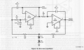
Current source I1 injects a small current pulse into the loop (simulating normal circuit noise) to start the oscillations.
The frequency is 2Hz instead of the stated 1Hz.
Not sure why the sine and cosine signals have different amplitudes.
The sine output also has high distortion.
The values for R3, R5, and R7 (my designators) are unusually high for an op amp circuit.
Would suggest values at least an order of magnitude lower values for a real circuit (with corresponding adjustment of the associated capacitor values).
Zeeus - why are you asking for 180 deg?
Only in case of an inverting amplifier we need a feedback network that can produce a phase shift of -180 deg.
But your circuit is quite different!
Of course, this is NOT a quadrature oscillator. Such an oscillator would consist of two integrating circuits.
Therefore, no surprise that both amplitudes are (a) not equal and (b) not in quadrature (90 deg).
This is a specific form of a phase shift oscillator - it consists of an inverting integrator (+90 deg) and a 2nd-order active lowpass in Sallen-Key-unity gain configuration (-90 deg at the pole frequency).
Hence, the loop gain can fulfill the oscillation condition (Barkhausen) at the pole frequency of the lopwpass.
* The phase of an (ideal) inverting integrator is always +90deg. Any other statement is wrong. (Don`t blindly follow any book statements when they are obviously false).
A real inverting integrator (with a real opamp) has a phase shift of +90 deg at one single frequency only.
* The 2nd-order (non-inverting) lowpass has a phase shift of -90deg at the pole frequency (in your example app. 0.5 Hz) and approaches a phase shift of -180deg for infinite frequencies only!
@ci139 - did you notice that the given circuit oscillates at ap.. 0.5 Hz (as expected in post 14 and shown in post 17) ?
So - why are you speaking about high-frequency properties?
1-st of all i was noting about my experience in compensating the LMx01/LMx08 for not the upper bandwidth edge operation
the 2-nd (for the sensitive or high speed op amps) such as and the LMx01/LMx08 appear to be (without the external compensation) . . . i was suggesting the minimum compensation scheme (otherwise they tend to oscillate around the expected output (median)) ...
... that appears to be both as the minimum-for-stable ((((and thus also the fastest for that particular compensation scheme))))
 Facebook
 Google
 GitHub
 Linkedin
 855 KB Views: 43


