Sine Wave filter for a VFD

Thread Starter

glcohen

Joined Feb 4, 2018
14
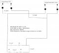
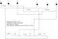
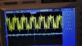
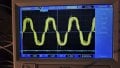
I have two failures of single phase 230v 50Hz 1/2Hp motors being driven by an Invertek Optidrive E1 size 2 in a fan coil; one after 18 years and the other after 8 months! To try to prevent a repeat I have used part of a three phase Mitsubishi suppression filter that I thought was a sine wave device but on closer examination seems to be a dv/dt filer. I enclose a jpg of its schematic. I have connected the incoming L and N to U and V and the outgoing to X and Y. This puts a series R/C filter across the output following the inductor. I enclose 'scope traces of before and after which shows considerable improvement. However, I now wonder if a better sine wave could be produced by changes to the circuit. I would be very grateful for further advice. Incidentally I have not been able to find anyone selling a proper single phase sine wave filter.
 

Attachments

MaxHeadRoom

Joined Jul 18, 2013
30,588
What do you mean by "used a part of the filter"?
It is used suppress HV HF components from the resultant VFD 3ph output.
I have never had any problems when a 3ph filter is used and the VFD set up correctly.
 

Thread Starter

glcohen

Joined Feb 4, 2018
14
Apologies - I should have made clear that this is a single phase VFD and a single phase motor. I have been able to use two of the phase connections of the three phase filter because of the the way it is wired - and as I have shown it does work to a degree.
 

Pyrex

Joined Feb 16, 2022
501
Hi
as I understand, thre's a single phase motor with capacitor? First of all, check the capacitor, they tend to lose capacity after some time.
And second. Whats is the minimum speed? Take in mind,motor cooling is much worse at low speed. Usually minimum speed is set to 25-30 percent.
The inverter produces a sufficiently good quality sinusoidal voltage and the motor works well with it, without any additional filters
 

Thread Starter

glcohen

Joined Feb 4, 2018
14
Its a single phase PSP motor. The capacitors were new with each of the previously failed motors and tested as being OK. Minimum speed is set to 26 hz but in practice the motor is always running at full speed (about 850 rpm on a 50Hz supply). The VFD output does not produce a good sinewave output as you can see from the attacked photos.
 

nsaspook

Joined Aug 27, 2009
16,263
Its a single phase PSP motor. The capacitors were new with each of the previously failed motors and tested as being OK. Minimum speed is set to 26 hz but in practice the motor is always running at full speed (about 850 rpm on a 50Hz supply). The VFD output does not produce a good sinewave output as you can see from the attacked photos.
Why do you think the output waveform is the problem?
When should I use an output filter with my Optidrive?
Optidrives, like the majority of other inverter drives have unfiltered outputs. In the majority of applications this will give satisfactory performance, however, in a small number of applications output filtering is strongly recommended to improve system functionality, reliability and longevity.

These applications include:
o Long motor cables, up to 200m
o High capacitance motor cables (ie typical "pyro" wire, used for fire protection)
o Multiple motors connected in parallel
o Motors without inverter grade insulation (typically older motors)

Motors without inverter grade insulation
Always check the motor specification and, if necessary, with the motor manufacturer to ensure the motor is rated for use with inverter drive products. Always follow any advice given on the requirement for using output filtering with Inverter product.
What exactly was the motor failure?
 

MaxHeadRoom

Joined Jul 18, 2013
30,588
In my experience, 1ph motor VFD's have never been successful,
Any reason you did not use a 3ph version. with 3ph motor?
Also the preferred supply is 240v 1ph supply for domestic versions, .
 

Thread Starter

glcohen

Joined Feb 4, 2018
14
Why do you think the output waveform is the problem?


What exactly was the motor failure?
Both motors had burnt out windings. They were probably not VFD rated motors but it has not been possible to confirm this. The output waveform from this sort of VFD is known to be problematic with non F insulated motors; these motors had B insulation. I am including a redrawn schematic which clarifies the present set up and the odd R/C network that has resulted between L and N with my using this three phase filter in a way that it was not designed for. I am simply seeking advise as to whether the present rather rough sinewave output can be improved on.
 

Attachments

Thread Starter

glcohen

Joined Feb 4, 2018
14
The motor was not my choice - its a Carrier FB4B fan coil which usually runs at one of three pre set speeds. The reason for adding a VFD to it was to allow closure of any of the 5 zones being fed by the fan coil whilst keep duct pressures unchanged. The VFD is controlled by a PID controller fed from a duct pressure sensor.
 

nsaspook

Joined Aug 27, 2009
16,263
Both motors had burnt out windings. They were probably not VFD rated motors but it has not been possible to confirm this. The output waveform from this sort of VFD is known to be problematic with non F insulated motors; these motors had B insulation. I am including a redrawn schematic which clarifies the present set up and the odd R/C network that has resulted between L and N with my using this three phase filter in a way that it was not designed for. I am simply seeking advise as to whether the present rather rough sinewave output can be improved on.
IMO don't waste time with trying to LPF the VFD modified sine waveform. Your current filter is about a good as it gets but really can't solve the problem of using the wrong type of motor for the job.
 

LowQCab

Joined Nov 6, 2012
5,101
Quite often modern Air-Handlers run their Motors close to the ragged-edge of their performance-envelope,
this means that they may not tolerate the extra stress imparted by a VFD.

The very best way to regulate Duct-Pressure is to restrict the Air-Inlet to the Coil with a Motorized-Damper.
This will simultaneously reduce the Current being drawn by the Motor, increasing it's Life-Expectancy.
But be careful in doing this,
because this may inadvertently cause a flow-back-up in the Condensate-Drain that
may require some slight "re-engineering" of the PVC-Trap and Drain-Pipe-Work.
These types of problems are also common with heavily-neglected, clogged-Air-Filters.

The Damper should be modified in such a way, ( physically bent or cut ),
so as to only limit it's maximum-restriction to the volume of Air-Flow needed
under low-demand-conditions to maintain an acceptable Duct-Pressure.

Also, You mentioned that the Factory-installed-Motors are "3-Speed".
Has any consideration been given to taking advantage of this 3-Speed option ?


A VFD is a brutally expensive way to limit Duct-Pressure.
.
.
.
 

Thread Starter

glcohen

Joined Feb 4, 2018
14
Quite often modern Air-Handlers run their Motors close to the ragged-edge of their performance-envelope,
this means that they may not tolerate the extra stress imparted by a VFD.

The very best way to regulate Duct-Pressure is to restrict the Air-Inlet to the Coil with a Motorized-Damper.
This will simultaneously reduce the Current being drawn by the Motor, increasing it's Life-Expectancy.
But be careful in doing this,
because this may inadvertently cause a flow-back-up in the Condensate-Drain that
may require some slight "re-engineering" of the PVC-Trap and Drain-Pipe-Work.
These types of problems are also common with heavily-neglected, clogged-Air-Filters.

The Damper should be modified in such a way, ( physically bent or cut ),
so as to only limit it's maximum-restriction to the volume of Air-Flow needed
under low-demand-conditions to maintain an acceptable Duct-Pressure.

Also, You mentioned that the Factory-installed-Motors are "3-Speed".
Has any consideration been given to taking advantage of this 3-Speed option ?


A VFD is a brutally expensive way to limit Duct-Pressure.
.
.
.
Thanks for your reply and your way of controlling air flow with an inlet damper - I had not thought of that. My system initially had a mechanical bypass damper on the outlet. This maintained a constant supply duct pressure by a counterweight system that vented air back to the return duct system. I do not remember why I decided to do away with this system - maybe I thought that I could save on electricity costs by not running the fan motor continuously at high speed; I think that the modern replacement for my FB4B fan coil has a factory installed variable speed fan motor. And yes, I had thought that a crude way of reducing duct pressure when vents were closed would be to switch to a lower fan speed - but this would not give the fine control of duct pressure that I naively thought would be straight forwards and reliable; which it was for 18 years.
 

LowQCab

Joined Nov 6, 2012
5,101
I think that You will find that tightly controlling Duct-Pressure really doesn't make
"all that noticeable" of a difference,
but it might look "right" on paper, ( or on a Computer-Screen ).

Forget about the Decimal-Points, they are completely irrelevant.

If your Fan is normally running on "High-Speed", I think that a "2-Stage" controller "switch"
would provide completely adequate control over Motor-Speed, and consequently, Duct-Pressure,
and even three-stages is easily-doable if you're feeling really "OCD" at the time,
after all, Duct-Pressure is not really a "precision-target" that must be maintained at any cost,
there's plenty of leeway, up or down, that will still provide quite transparent performance to the occupants,
and after all, they are the ones that count.

Actually, I've had some serious issues with "occupants" and accessible Thermostat-Controls,
which I found some very creative ways of "skirting-around", but that's another story for another time.

And, FWIW, I didn't think anyone still used High-Pressure-Ductwork in AC-Systems anymore.
For some odd reason I got the idea that High-Pressure-Duct-Systems just kinda "went out of style"
sometime in the '70's, along with the infamous Honeywell-fully-Pneumatic-Control-Systems !!!
.
.
.
 

Thread Starter

glcohen

Joined Feb 4, 2018
14
I think that You will find that tightly controlling Duct-Pressure really doesn't make
"all that noticeable" of a difference,
but it might look "right" on paper, ( or on a Computer-Screen ).

Forget about the Decimal-Points, they are completely irrelevant.

If your Fan is normally running on "High-Speed", I think that a "2-Stage" controller "switch"
would provide completely adequate control over Motor-Speed, and consequently, Duct-Pressure,
and even three-stages is easily-doable if you're feeling really "OCD" at the time,
after all, Duct-Pressure is not really a "precision-target" that must be maintained at any cost,
there's plenty of leeway, up or down, that will still provide quite transparent performance to the occupants,
and after all, they are the ones that count.

Actually, I've had some serious issues with "occupants" and accessible Thermostat-Controls,
which I found some very creative ways of "skirting-around", but that's another story for another time.

And, FWIW, I didn't think anyone still used High-Pressure-Ductwork in AC-Systems anymore.
For some odd reason I got the idea that High-Pressure-Duct-Systems just kinda "went out of style"
sometime in the '70's, along with the infamous Honeywell-fully-Pneumatic-Control-Systems !!!
.
.
.
Its not high pressure (its about 0.1" water). Closing vents and leaving the fan at high speed does made a difference. It makes vents which were previously silent noisy.
 

LowQCab

Joined Nov 6, 2012
5,101
What is "dol" ? in ~60-years I've never heard of that one.
Evidently it stands for "Direct-On-Line", but what does that mean ?, as opposed to what ?

I get so tired of having to remember hundreds of Acronyms
just so that people can be lazy and type fewer letters.

It's true, that if a Motor is not running at it's rated Power that it may
be operating in a less Efficient part of it's Power-Curve,
but it will still be using less overall Power, thus reducing the Electrical costs, and Waste-Heat output.

Less-Load equals Less-Current,
the Voltage doesn't change,
therefore less Power is consumed.
.
.
.
 

Thread Starter

glcohen

Joined Feb 4, 2018
14
What is "dol" ? in ~60-years I've never heard of that one.
Evidently it stands for "Direct-On-Line", but what does that mean ?, as opposed to what ?

I get so tired of having to remember hundreds of Acronyms
just so that people can be lazy and type fewer letters.

It's true, that if a Motor is not running at it's rated Power that it may
be operating in a less Efficient part of it's Power-Curve,
but it will still be using less overall Power, thus reducing the Electrical costs, and Waste-Heat output.

Less-Load equals Less-Current,
the Voltage doesn't change,
therefore less Power is consumed.
.
.
.
I found this:

Direct on line (DOL) motor starting is when a motor is started at full load, with full line voltage applied to motor terminals. As this causes the motor to draw a large amount of current, it is only suitable for motor powers up to 4Kw, with a maximum motor size of 10Kw connected this way.
 

MisterBill2

Joined Jan 23, 2018
27,258
45 years ago at the research lab of a medical school in south Louisiana there was a problem with lab techs closing off AC vents instead of raising the thermostat setting. The solution involved not replacing the failed AC system components during the July and August. Experience can be a brutal teacher but some folks will not learn any other way.

An induction motor running at 26 Hz is going to get very warm. And if it is an actual 60 Hz 3 speed motor the lowest speed would be about 850 RPM. So a better scheme will be to connect the lowest speed tap, and if there is a need for greater speed in some conditions, the a scheme to switch speed taps when more speed is needed. That can totally avoid the VSD package and probably save even more electricity.
 
Top