Simplifying combination circuit and finding values.

Thread Starter

Bobby_Typhoon

Joined Sep 1, 2014
3
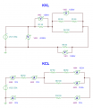
So I have a combination circuit that I am trying to simplify, however I become stuck after I combine loads 2, 3 and 4. I add the resistances of load 2 and load 3 to get my total between those two (100Ω) and turn them into load 2/3. Then I perform the Req = 1/{(1/R1)+(1/R2)+(1/R3)..+(1/Rn)} to get the total of load 2/3/4 (50Ω). Then I take the resistances of load 1 (50Ω) added to the resistance of load 2/3/4 (500Ω) added to the resistance of load 5 (50Ω) to get my total resistance for the circuit which is 150Ω.

Now assuming that is correct I multiply 150Ω by 37A to get 5550V. Then I take the 5550V and multiply that by 37A to get the power total of 205350W. After that I then placed the 37A on load 1, the combined load 2/3/4 & load 5 since they are now in series. I then solved for the remaining power and voltage on those loads and since they all have the same resistance value (50Ω) and amperage (37A) I came out with 1850V and 68450W, which when added up since I am following the series rules now I get the total voltage of 5550 and the total wattage of 205350.

So I am feeling pretty good about myself as I believe I have done everything correctly to this point, however as I look at my worksheet I become completely and utterly lost as to finding the individual values of voltage, amperage and wattage for load 2, load 3, and load 4. I have gone back over my notes from class and I am assuming I forgot to write something down or am just not getting it cause I can't figure out how to break the combined load 2/3/4 back down into it's separate parts. I have read through the book we're using and that doesn't seem to help either. Any help and instruction would be greatly appreciated.

homework circuit.png
 

JoeJester

Joined Apr 26, 2005
4,390
Redraw your circuit until you end up with a single resistor and the battery.

Show each step that you re-drew. You should end up with three diagrams showing a single equivalent resistance and the battery. You can answer the totals to the left.

Then do the same E I R P calculations for each of the circuits as you work back to the original. KVL and KCL will guide you for the E I R P calculations for the individual resistors.

Your total calculations are correct. Use KVL and KCL to solve the remaining.
 
Last edited:

MikeML

Joined Oct 2, 2009
5,444
First, a current source is drawn differently than a voltage source. I assume that you intended conventional current to flow downwards in your figure.

When describing voltages at the nodes of a circuit like this, it is also common practice to pick one of the nodes and call it "ground", or "zero V", or "the node with respect to all other voltages are measured"...

Here is a summary of all the voltages at the nodes I have labelled a, b, c, d, and gnd. Also shown are the currents that flow in all of the components

65.jpg

Do you understand why all of the node voltages are negative?

Can you tell me what is the voltage across Resistor R1? Which end is more positive?
 

shteii01

Joined Feb 19, 2010
4,644
Like Joe said. You did the simplification, you have: R=150 Ohm, I=37 A, V=5550 V.

R2+R3 and R4 form current divider.
R2+R3=50 Ohm+50 Ohm=100 Ohm.
R4=100 Ohm
So your current divider has two branches, each branch is 100 Ohm, which means that the current entering the divider will be split equally between the branches. What is the current entering the divider? 37 A enters the divider. Therefore each branch will have 37 A/2=18.5 A.

Now you know all the resitances and all the currents. Find voltages and power.
 
Last edited:

Thread Starter

Bobby_Typhoon

Joined Sep 1, 2014
3
Redraw your circuit until you end up with a single resistor and the battery.

Show each step that you re-drew. You should end up with three diagrams showing a single equivalent resistance and the battery. You can answer the totals to the left.

Then do the same E I R P calculations for each of the circuits as you work back to the original. KVL and KCL will guide you for the E I R P calculations for the individual resistors.

Your total calculations are correct. Use KVL and KCL to solve the remaining.
Thank you for the response, I have been re-drawing the circuit on scrap paper, and it does help. However we haven't gone over Kirchoff's laws in class, only Ohm's law and Watt's law. I don't know if those are similar to Kirchoff's laws at all, I looked them up and it only further confused me.


First, a current source is drawn differently than a voltage source. I assume that you intended conventional current to flow downwards in your figure.

When describing voltages at the nodes of a circuit like this, it is also common practice to pick one of the nodes and call it "ground", or "zero V", or "the node with respect to all other voltages are measured"...

Here is a summary of all the voltages at the nodes I have labelled a, b, c, d, and gnd. Also shown are the currents that flow in all of the components

View attachment 72524

Do you understand why all of the node voltages are negative?

Can you tell me what is the voltage across Resistor R1? Which end is more positive?
I just drew the diagram as it is written on the worksheet, but in class we have been working with the current flowing downwards. I am going to assume the node voltages are negative because the flow goes from negative to positive? I believe the voltage across Resistor R1 is 1850V, and I assume the end closest to node A is the more positive end?


Like Joe said. You did the simplification, you have: R=150 Ohm, I=37 A, V=5550 V.

R2+R3 and R4 form current divider.
R2+R3=50 Ohm+50 Ohm=100 Ohm.
R4=100 Ohm
So your current divider has two branches, each branch is 100 Ohm, which means that the current entering the divider will be split equally between the branches. What is the current entering the divider? 37 A enters the divider. Therefore each branch will have 37 A/2=18.5 A.

Now you know all the resitances and all the currents. Find voltages and power.
If the current divider has three branches would the current entering the branches then be split into thirds? If the R2+R3 branch has 70 Ohms and the R4 branch has 100 Ohms, would the current still be split equally between both branches, just the current values on each separate resistor change?
 

JoeJester

Joined Apr 26, 2005
4,390
If the R2+R3 branch has 70 Ohms and the R4 branch has 100 Ohms, would the current still be split equally between both branches, just the current values on each separate resistor change?
The short answer is NO. Only equal branches split the current evenly.

From wiki

KCL - At any node (junction) in an electrical circuit, the sum of currents flowing into that node is equal to the sum of currents flowing out of that node.

KVL - The directed sum of the electrical potential differences (voltage) around any closed network is zero.

In practice, if you added the voltage drop of R1, R4, and R5 that must equal the source voltage.
The 37 amperes entering in the parallel branch (R2+R3) || R4 must exit equaling 37 amperes.

Edited to add illustration:
 

Attachments

Last edited:

Thread Starter

Bobby_Typhoon

Joined Sep 1, 2014
3
The short answer is NO. Only equal branches split the current evenly.


In practice, if you added the voltage drop of R1, R4, and R5 that must equal the source voltage.
The 37 amperes entering in the parallel branch (R2+R3) || R4 must equal 37 amperes.
So how would you find the current split on branches that aren't equal? My teacher did explain the voltage drop equals the source, she just didn't mention Kirchoff by name. I still feel a little overwhelmed, but working on this problem has made things make a little more sense.
 

crutschow

Joined Mar 14, 2008
34,420
The voltage across a parallel branch is equal on both sides of the branch. The current divides inversely according to the relative resistance of each branch. Thus a branch with twice the resistance would carry 1/2 the current of the other branch. The current of each branch equals the voltage across the branch divided by the branch resistance.
 

shteii01

Joined Feb 19, 2010
4,644
If the current divider has three branches would the current entering the branches then be split into thirds?
It would split into three separate currents. The amount of current going into each branch depends on the resistance present in the branch.


If the R2+R3 branch has 70 Ohms and the R4 branch has 100 Ohms, would the current still be split equally between both branches,
No. There is a formula for finding current in each branch of current divider. I am sure your textbook has it. I suggest you read it, then apply it.
 
Top