Facebook
 Google
 GitHub
 Linkedin
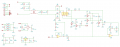
I'm looking at this output driver circuit, and two things come to mind:
1) It appears to be more complex than it could be
2) I don't like the 170-volt DC supply (D6-D9 bridge to F2 section), and know it's possible to run this same circuit with 12VDC, which then loops back to observation 1.
The pulse signal is a square wave with variable duty cycle, and SW1 is a representation of the PIA output that enables this circuit.
The 'Drive' output feeds a coupling transformer to the next stage.
I anticipate I would be keeping everything up to C40, it's just C40 and everything to the right I'd like to simplify, mainly to get the output to a safer value and eliminate T1 (custom transformer)...
Could I use an op-amp and a push-pull pair of transistors?
Attachments
-
 40.8 KB Views: 23