simplest opamp triangle or sine wave ascillator for breadboards

GopherT

Joined Nov 23, 2012
8,009
For your first question, try an experiment...
Connect a 1k ohm resistor across you output and ground when you have the microphone set up and listen, then try with a 100 ohm, a 10 ohm and a 4 ohm (same as your speaker).

Do this and report back

EDIT: very nice "sci fi" sounds!
 
Last edited:
Thread Starter

dentaku

Joined Jul 29, 2013
45
I see someone actually answered. Thanks for actually trying to help the beginners.

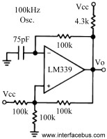
So do you mean to connect different sized resistor between the triangle output (the point between the capacitor and pin 4 of the LM339N?) and ground? while I have it connected to the mic in of the computer and see what happens?

Or do you mean the "THE output" as in pin 2 "Vo" of the LM339N? where I get a nice square wave that outputs fine on the little 4ohm speaker unlike the triangle.

I've tried both and the sound just stops completely.

I'm assuming the solution to being able to hear the triangle wave by directly connecting a speaker to the breadboard would involve some kind of buffer that goes between the output and the speaker??? I don't know, I'm just guessing :) I still don't understand impedance and such.

For your first question, try an experiment...
Connect a 1k ohm resistor across you output and ground when you have the microphone set up and listen, then try with a 100 ohm, a 10 ohm and a 4 ohm (same as your speaker).

Do this and report back

EDIT: very nice "sci fi" sounds!
 

GopherT

Joined Nov 23, 2012
8,009
To understand impedance, think of the water supply (plumbing) in house where a stone is stuck in the main water pipe. When you measure the water pressure with no water running, there is plenty of pressure and you think you will be able to easily rinse the soap off your body. Then, you flush a toilet while measuring the pressure and realize that the stone is preventing flow and pressure falls drastically until the toilet is refilled. The rock is a resistance that impedes flow. A high impedence (resistance) output.

Removing the stone will lower the impedence of the output. Now you can flush the toilet and notice almost no pressure drop.


In a circuit with a high impedence output, your output voltage drops dramatically if you connect a load that draws more current than the circuit output can provide.

The reverse is not so much of a problem in audio frequency systems (when you connect a small load (high resistance) to a circuit that can easily provide much more current than the large value resistor will need).
 

Thread Starter

dentaku

Joined Jul 29, 2013
45
I decided to try again and finally took the time to use an LM358N to make a voltage follower and now the triangle wave can be heard out of the speaker just like the squarewave always has.

Since I was halfway there already I then used the LM358N to make a non-inverting amplifier and it's even better now.

I guess I'm going to have to tear it all apart and use something other than an LM339N comparator to generate the squarewave so I only have to use one IC for the whole thing.
Since I have a known working LM358 I might as well just build the VCO that's in the National Semiconductor datasheet for it which uses both halves of the opamp and outputs a square and a triangle.
 

Shagas

Joined May 13, 2013
804
Are you using the LM358 directly to power a speaker?
If you are then it might be a trap because your speaker will be pulling too much current from the LM358 which will cause it to clip and 'square' any wave you are inputing .
 
Top