Simple RF Transmitter Issue

Thread Starter

Đorđe Jocić

Joined Aug 15, 2019
14
Hello there, I hope that you are having a great day!

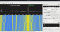
I started experimenting with RF few weeks ago, and managed to create two working transmitter circuits - using a 555 Timer & 40MHz Quartz Crystal Oscillator. I could easily test them by monitoring the appropriate frequency using a generic RTL-SDR Receiver Dongle & GQRX on Linux, which is all fine and dandy.

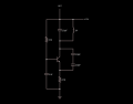
Last couple of days I've been trying to create one that relies on an LC Oscillator, but just couldn't manage to generate a signal. I used a 0.5mm copper wire, bendy as hell, to create a ~480nF coil by winding it five times over a 10mm cylinder. Coupled with a 10pF capacitor, the frequency of the oscillator should have been ~72Mhz.

What am I doing wrong?
 

Attachments

DickCappels

Joined Aug 21, 2008
10,152
That doesn't look like it would oscillate. Suggested modifications: Use a 2N3904 (Ft > 300 MHz), put a 470 ohm resistor between the emitter and ground, put a 5 pf capacitor between the collector and emitter, put a .001 uf capacitor from the base to ground and a 15k resistor from base to ground. I would not bother with the 1k resistor between the antenna and the collector, indeed it is best to try the oscillator without an antenna first. All capacitors mentioned should be ceramic.

Another member had difficulty with this kind of oscillator recently. Below is a link to that thread.
https://forum.allaboutcircuits.com/threads/colpitts-oscillator-fm-transmitter.150002/
 

Thread Starter

Đorđe Jocić

Joined Aug 15, 2019
14
The updated circuit (attached below) worked! I didn't have some parts you suggested so I had to use 2N2222 transistor, and two 10pF capacitors placed in series instead the 5pF one. Trying to place a capacitor of different value affected transmission - stopped it. Additionally, moving the hand near the inductor caused the transmission frequency to fluctuate.
 

Attachments

Audioguru again

Joined Oct 21, 2019
6,674
You wrongly have your antenna connected to the +5V power supply instead of being connected to the output (collector) of the transistor.
You also wrongly have a huge capacitor and a huge coil that are tuned to a very low frequency.

Yes, the antenna should be connected directly to the tuned LC so of course the frequency changes of something moves towards or away from the antenna.

In my FM transmitter I fixed the problem by adding a broadly tuned RF buffer amplifier.
I also added a low-dropout voltage regulator so that the frequency would not change as the battery voltage ran down.
 

Attachments

Janis59

Joined Aug 21, 2017
1,834
1)555 have maximum-maximorum frequency 1,5 MHz (and stable work for 1 MHz) thus it is completelu unutilizabla as generator for transmitter (except the telegraph modulator).
2) Resonant amplifier for Colpitts oscillator is rather well working and stable solution, however output power wonder if is over 50 mW thus the distance hardly beyond of 100 meters. Only solution to beat a 250 mW and half-kilometer is pushpull output or more expensive RF power transistor alternatively.
 

Thread Starter

Đorđe Jocić

Joined Aug 15, 2019
14
Yes, the antenna should be connected directly to the tuned LC so of course the frequency changes of something moves towards or away from the antenna.
Thanks for the tip! Moving the antenna to the collector of the transistors stopped the frequency fluctuations - but not completely. Additionally, I was only able to get the tank to resonate at ~40Mhz, changing the diameter of the inductor and the number of turns didn't seem to have desired effect - it was either ~40Mhz or nothing at all. Could this be because of the breadboard and the parasitic inductance?

What is the diameter of the wire you used to create a 0.1µH inductor?

1)555 have maximum-maximorum frequency 1,5 MHz (and stable work for 1 MHz) thus it is completelu unutilizabla as generator for transmitter (except the telegraph modulator).
It was extremely easy to make, and strangely enough I was able to transmit knocks, and barely comprehendable speech, through an electret microphone. It served as a good introduction to RF circuits.
 

DickCappels

Joined Aug 21, 2008
10,152
(Some text removed for clarity)

Additionally, I was only able to get the tank to resonate at ~40Mhz, changing the diameter of the inductor and the number of turns didn't seem to have desired effect - it was either ~40Mhz or nothing at all. Could this be because of the breadboard and the parasitic inductance?

What is the diameter of the wire you used to create a 0.1µH inductor?
Yes, it certainly could be the extra capacitance and stray inductance on that plastic breadboard.

1581754312154.png

For FM transmitters I usually use 5 to 8 turns of #22 air core but wound on an approximately 5.0 mm drill bit (the smooth part!) and then slide it off. The wire is usually stretched a little bit prior to winding to make it give up "clear" the wire's "shape memory"

In the circuit above, the operating frequency was adjusted by spreading/compressing the windings.
 

Audioguru again

Joined Oct 21, 2019
6,674
Hi Dick,
Your stereo mixing resistors have a very high resistance of 470k then doesn't the 0.001uF capacitor (grounding the transistor base at RF frequencies) cut audio frequencies above 680Hz? I guess the input impedance of the transistor will increase the cutoff frequency a little.
It produces the opposite of the pre-emphasis that is needed. A normal FM radio will sound very muffled.
 

DickCappels

Joined Aug 21, 2008
10,152
Yeah, I know! I tired pre-emphasis on a few of my transmitters but they never sounded different whether switched in or out. As I recall you have really nice hearing aids and you can probably tell the difference easily. I posted the schematic so Đorđe Jocić could get an idea of a tank circuit that works on the FM band.
 

Audioguru again

Joined Oct 21, 2019
6,674
On the other website forum I complain about the Fuzz and Overdrive severe distortion of rock "music" because the musicians are deaf to it.

When I was a teenager I heard and complained about ultrasonic burglar alarms that were turned on day and night because "they were inaudible".

I can hear kids coming around a corner before I see them. They have their earphones too loud.

My hearing aids have noise reduction, compression and left-right/front-back directionality. Their Extra Sensitivity and Muting Functions are also useful.
 

Janis59

Joined Aug 21, 2017
1,834
Circuit at post No 9 will always insert some frequency deviation into system (surplus purely thermal). Just antenna without of proper tuning box is complex imedance having as well inductive and capacitative components which are dependant on distance to gnd, to human body and even objects in antenna view zone, antenna angle and length etc etc. And both L and C are virtually parallel to the resonant tank.
 

Thread Starter

Đorđe Jocić

Joined Aug 15, 2019
14
Thank you all for the great tips & examples, I have finally managed to make a working RF module with a stable frequency and have attached the circuit below. While there were issues with parasitic inductance/capacitance, the almost fixed ~40MHz frequency was due to wrong wiring - yet another derp moment in the world of electronics.

One note, I could only make the circuit osculate with the 50pF capacitor across the collector & emitter. As I currently only have a cheap multimeter at my disposal, that will remain a mystery for now.

This may have been the most difficult project I have done so far, but it was fun nonetheless.
 

Attachments

DickCappels

Joined Aug 21, 2008
10,152
Congratulations! RF circuits can seem like pure magic.

If your ground symbol is "RF ground" (a made-up term) your antenna should not radiate, but if it gives you what you want, use it. Do you have a small capacitor between +5V and ground? That's a pretty good thing to do, I am sorry I missed mentioning that earlier on.
 

Janis59

Joined Aug 21, 2017
1,834
Cap across C&E is the positive loop cap. It adjust any hardness or softness of generation regime. The critical one is where oscillation amplitude becomes unstable and lower as Vcc. Then must take a SLIGHTLY larger cap. This hard-to-maild transit may happen be ugly sharp if the Q-factor of circuit is too small or the bjt have too small f(t). Apply the faster bjt and inventarisate what loss have in tank (and C(ce) as well). Or does the base is short-circuted to the gnd by means of AC (cap). Probably You applied the cap what is very slow, or it loss factor is high? And last is the pcb material- if dark yellow or brown - never use it above 10 MHz, 27 already demands a colourless. Best of best pcb have LF= 0,0003, normal have 0,03 and bad have 0,3.
 
Top