Simple non-inverting Amplifier Not working

Thread Starter

Mohamed_Rushdyy

Joined Nov 4, 2016
18
It is difficult to see where the wires go because of the shadows in the picture but I think there are several errors in the connections, in particular concerned with things which should be connected to U1 pin 6 (the mid- rail '0V') but are not.
The bottom end of R4 is connected to +15V not the mid-point ground.
I can see no connection to U1 pin 7
U1 pin 6 appears to be connected to +15V by a thin green wire (suspect that wire should go to pin 7, not pin 6)
The white wire from your input (not sure which wire it is) isn't connected to U1 pin 6.

Please check carefully the layout compared to the circuit diagram.
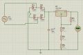
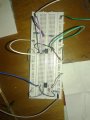
OK although i'm sure i connected the previous circuit right but i'v removed all the items and reconnected it again.
And to put you on the whole picture,I'm using a variable power supply using an LM317 variable regulator.(The schematic is attached)
also the input signal is coming form an arduino from the PWM pins (5 for analog) where i'v adjusted it to 1.00 volts exactly.
 

Attachments

Thread Starter

Mohamed_Rushdyy

Joined Nov 4, 2016
18
It is difficult to see where the wires go because of the shadows in the picture but I think there are several errors in the connections, in particular concerned with things which should be connected to U1 pin 6 (the mid- rail '0V') but are not.
The bottom end of R4 is connected to +15V not the mid-point ground.
I can see no connection to U1 pin 7
U1 pin 6 appears to be connected to +15V by a thin green wire (suspect that wire should go to pin 7, not pin 6)
The white wire from your input (not sure which wire it is) isn't connected to U1 pin 6.

Please check carefully the layout compared to the circuit diagram.
And this is the circuit reconnected and better capturing.
 

Attachments

AlbertHall

Joined Jun 4, 2014
12,346
The new breadboard layout is not correct. In the section below, pin 6 of U1 is connected by the red wire to the bottom row of the breadboard. That row is connected by the grey wire to the other row near the bottom and that is the +15V supply.

How are the two rows at the bottom connected within the breadboard? Are the rows split in the middle, and are the two rows connected toe each other or separate?

upload_2016-11-5_11-43-30.png
 

Thread Starter

Mohamed_Rushdyy

Joined Nov 4, 2016
18
The new breadboard layout is not correct. In the section below, pin 6 of U1 is connected by the red wire to the bottom row of the breadboard. That row is connected by the grey wire to the other row near the bottom and that is the +15V supply.

How are the two rows at the bottom connected within the breadboard? Are the rows split in the middle, and are the two rows connected toe each other or separate?

View attachment 114828
The breadboard is separated in that part.each five groups are connected together this is the "Pro-Ject board gL 12".google it to see its design
And thanks a lot for helping me.:):)
 

WBahn

Joined Mar 31, 2012
30,060
The breadboard is separated in that part.each five groups are connected together this is the "Pro-Ject board gL 12".google it to see its design
And thanks a lot for helping me.:):)
Okay, I Googled it and got lots of hits, but the first several I tried provided no information on the internal connections. Looking further revealed images that were contradictory. Don't make us hunt for information we need from you. YOU find a page that shows the internal connections of YOUR board and then post a link to THAT page.
 

Thread Starter

Mohamed_Rushdyy

Joined Nov 4, 2016
18
The new breadboard layout is not correct. In the section below, pin 6 of U1 is connected by the red wire to the bottom row of the breadboard. That row is connected by the grey wire to the other row near the bottom and that is the +15V supply.

How are the two rows at the bottom connected within the breadboard? Are the rows split in the middle, and are the two rows connected toe each other or separate?

View attachment 114828
I have solved the problem.
All the connections are fine and right.The problem was in the arduino.Because of the PWM pins in the arduino the input signal was oscillating alittle and this oscillation was amplifier and was found on the output.So when i use my voltmeter it only reads the dc voltage and it ignores the AC.Of course i wouldn't have found this without the usage of the oscilloscope which i didn't have an access to till today.

Thanks alot for your time and your help and i wish i can pay you back one day...
Thanks again
 

Thread Starter

Mohamed_Rushdyy

Joined Nov 4, 2016
18
Okay, I Googled it and got lots of hits, but the first several I tried provided no information on the internal connections. Looking further revealed images that were contradictory. Don't make us hunt for information we need from you. YOU find a page that shows the internal connections of YOUR board and then post a link to THAT page.
Well I really appreciate you helping me and i'm trying my best to give you all the information you need but i'v tried to find any design of the breadboard online with no hope.I'v also tried to explain the breadboard design myself here but i didn't find the right words for it so I typed its name hoping that you will have better luck than mine.Also this breadboard design is very famous so i assumed that you knew it earlier.
Well the problem in my circut wasn't the breadboard but the arduino's PWM pins
Thanks for your time.
 
Top