Simple n-channel MOSFET circuit not working

Thread Starter

Tom Auger

Joined Aug 9, 2017
13
The help I've received in the general channel around MOSFETs has given me the confidence to attempt a simple circuit using a 12V 20A power supply to drive a ton of 12V white LEDs, with 5V PWM output from an Ardunio Nano going into a logic-level n-channel MOSFET (P30N06LE).

Unfortunately the story doesn't end there (otherwise I wouldn't be writing this post): I have tried a number of ways to wire this up with very unsatisfactory results.

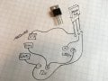
Here are my most recent attempts. In later attempts I threw in a resistor at random because I've seen them in some examples on the web, though I really don't know what function they would serve.

I actually had the whole thing working on the breadboard at one point (without resistors) - the LEDs were pulsing as intended, but something was lost in translation when I moved it to the soldering stage (and incidentally started powering the Arduino off the same power rail as the LEDs) and now I'm back to square one.

FullSizeRender 2.jpg IMG_1302.JPG IMG_1303.JPG

I think the datasheet is this one: https://www.sparkfun.com/datasheets/Components/General/RFP30N06LE.pdf, which is why I've labeled the GDS pins the way I have.

Any help would be appreciated, and explanations doubly so. Thank you in advance for taking the time to answer what I'm sure is a question of the most basic nature.
 

Attachments

crutschow

Joined Mar 14, 2008
34,285
You show the LED connected to the MOSFET source in on drawing and the MOSFET drain in another, so which is it?
It should be connected to the drain.

If it worked on the breadboard but not after soldering, then there's obviously something different between the two circuits. :rolleyes:
 

ebeowulf17

Joined Aug 12, 2014
3,307
Are these individual LEDs, or are they part of a strip? The strip would almost certainly have the required resistors built in. Individual LEDs would almost certainly require external resistors or they'd be fried rather quickly.

Also, have you been paying attention to the polarity of the LEDs? Any chance you connected some or all of them backwards?
 

ebeowulf17

Joined Aug 12, 2014
3,307
This is not even a circuit to begin with!
"12V, 20A" is 240W, you will need a fan to cool this off. Can your transistors bare it?
Just because a power supply is rated at 20A doesn't mean the circuit will draw that much current. I'm betting the thread starter doesn't have 20A worth of LEDs here.

Even if I'm wrong and this is meant to be a high power project, the transistors in a well laid out circuit won't be dissipating anywhere near the 240W you mentioned. For example a MOSFET with Rds-on of 8.7 milli-ohms would be dissipating 3.48W at 20A. Admittedly, that's a fair bit of heat to dissipate, but it's well within the range of TO-220 package with appropriate heat sinking.
 

ArakelTheDragon

Joined Nov 18, 2016
1,362
I didnt say that he will certainly need it, but he does say only this, so I prefer to risk and ask. If he by some chance raises the current, everything will blow.
 

ebeowulf17

Joined Aug 12, 2014
3,307
I didnt say that he will certainly need it, but he does say only this, so I prefer to risk and ask. If he by some chance raises the current, everything will blow.
Fair enough.

Also, I admit that I didn't realize there was already a datasheet linked for the MOSFET the thread starter is using, and I did my calculations based on a different (better) MOSFET. The one currently being used would dissipate 5-6 times as much heat as I originally calculated.
 

ArakelTheDragon

Joined Nov 18, 2016
1,362
I think this circuit is easy, he just has 1 diode to flash with a PWM pin. I dont think it takes much, plus why does everyone use arduino when all the experts complain its bad?

I dont know the voltage of white LEDs, but I dont think its "12V". You will need to adjust the resistors in order to get the proper voltage you need over the diodes and proper current through them.
 

Attachments

Jony130

Joined Feb 17, 2009
5,487
Why would it be always on?
Almost all discrete MOSFETs will have a parasitic diode called body diode.
And this diode is even shown on your diagram.
Maybe I turned the transistor
But now you will have another problem. To turn ON the N channel MOSFET the gate voltage needs to be 3..5V higher then the source voltage.
But now after you flip the MOSFET the gate voltage needs to be higher than Vled + Vres + Vgs.
 
Last edited:

ArakelTheDragon

Joined Nov 18, 2016
1,362
I know about the reverse diode, 10x for the explanation. I don't know the terms in English (what the heck is a bode diode).

I am just rewriting the circuit from the first post. If I switch the logical MOS with 20KHz, "5v", what will happen?
 

ArakelTheDragon

Joined Nov 18, 2016
1,362
I thought that logic MOS transistors in key mode, need to be switched at a high frequency with "5v" on the gate? While power MOS ones need "12-15v" on the gate and then they work in key mode switching a higher voltage on the drain?
 

Jony130

Joined Feb 17, 2009
5,487
I thought that logic MOS transistors in key mode, need to be switched at a high frequency with "5v" on the gate?
The problem is elsewhere.

Look at this example
12.png

Do you understend why the voltage at RLOAD1 is 1.96V and at RLOD2 is 12V ?
Tip. remember the II Kirchhoff's law V1 = Vgs1 + V_Rload1 and for the secend circuit V4 = V_RLOAD2 + Vds.
 

ArakelTheDragon

Joined Nov 18, 2016
1,362
The voltage on V R load 2 is "12V" because the load is in the drain and the whole voltage is applied on the resistor. The loses over the channel "DS", should be " Is*R(DS)". How much is the resistance of the channel and why do we get "1.96v"/at the first circuit? Isn't key mode designed to switch the supply voltage with very small losses.
 

hobbyist

Joined Aug 10, 2008
892
In later attempts I threw in a resistor at random because I've seen them in some examples on the web, though I really don't know what function they would serve.
The function of that resistor is to keep the mosfet gate grounded, otherwise any sparatic voltages in the circuit or static electricity in the air close to the gate terminal could cause the mosfet to trigger on and stay on, without a valid input.
 
Top