Simple level shifter

Thread Starter

cmartinez

Joined Jan 17, 2007
8,758
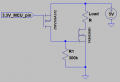
I need a level shifter so that a 3.3V output from an MCU can trigger the input of an Nfet (TK40E06N1) whose requirements are that at least 4.5V are applied to its gate.

The Nfet works fine if I apply 5V to its gate. But what I haven't been able to understand, is how to level-shift the 3.3V trigger from my MCU.

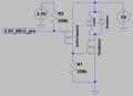
It's imperative that as little current as possible is used in the circuit, that's why I tried to sim this arrangement in LTSpice, but I can't seem to make it work.


The output reads at the same level as the input, and not at the 5V that I actually want:
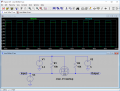
upload_2018-7-7_15-11-57.png

What am I doing wrong?
 

Attachments

wayneh

Joined Sep 9, 2010
18,100
I'm confused by the circuit but here's a stab. MOSFET non conducting, output must be 5V. MOSFET conducting, Vout = 0 if V3 is low and 3.3V if V3 is high.

The part that's confusing me is that the gate voltage will never be >3.3V, right? I thought you wanted 5V on the gate to turn it fully on?
 

Thread Starter

cmartinez

Joined Jan 17, 2007
8,758
I'm confused by the circuit but here's a stab. MOSFET non conducting, output must be 5V. MOSFET conducting, Vout = 0 if V3 is low and 3.3V if V3 is high.

The part that's confusing me is that the gate voltage will never be >3.3V, right? I thought you wanted 5V on the gate to turn it fully on?
Maybe I didn't explain myself. I want the output of this circuit to drive another mosfet's gate at 5V.
 

dl324

Joined Mar 30, 2015
18,308
It's imperative that as little current as possible is used in the circuit, that's why I tried to sim this arrangement in LTSpice, but I can't seem to make it work.
I'm not sure why LTSpice isn't showing 5V at the output when the input is at 3.3V. The MOSFET should be off, and the output should be pulled to 5V by R2.
 

Thread Starter

cmartinez

Joined Jan 17, 2007
8,758
I'm not sure why LTSpice isn't showing 5V at the output when the input is at 3.3V. The MOSFET should be off, and the output should be pulled to 5V by R2.
Could it be a faulty spice model for the 2N7000? ... I've already tried the 2n7002 model, to no avail...
 

Thread Starter

cmartinez

Joined Jan 17, 2007
8,758
With a Vgs of 0V, it should be off. Idss is 1uA at 25C, so Vout should be more like 4.99V.
I know ... I've tried the sim using a different mosfet model, and it's still not working. Funny thing is, I have this same arrangement working using a ZVNL120A nFet, and it works just fine in the real world. But using 4k7 for R1 and R2.
 

dl324

Joined Mar 30, 2015
18,308
I know ... I've tried the sim using a different mosfet model, and it's still not working. Funny thing is, I have this same arrangement working using a ZVNL120A nFet, and it works just fine in the real world. But using 4k7 for R1 and R2.
It's the simulator because we know the circuit works. There are many commercially available circuits using 10k resistors; though they usually use a low Vth device.

2N7000 is marginal at 3.3V, but Rds (on) is negligible with a 10k pull-up. So the output will still be recognized as a LOW.
 

Thread Starter

cmartinez

Joined Jan 17, 2007
8,758
It's the simulator because we know the circuit works. There are many commercially available circuits using 10k resistors; though they usually use a low Vth device.

2N7000 is marginal at 3.3V, but Rds (on) is negligible with a 10k pull-up. So the output will still be recognized as a LOW.
What the heck, then... I'm just gonna breadboard it and test it, see how it goes... I'll be back with the results as soon as that happens.
 

Thread Starter

cmartinez

Joined Jan 17, 2007
8,758
Hello,

When you could get hold of an BS107, you would have a gate threshold of max 2 Volts.

Bertus
Good idea ... maybe I should just go with a small p-channel mosfet and use it to drive the n-fet's gate directly, like this:

upload_2018-7-7_17-0-21.png

I have a few ZVP2106ASTZ laying around, maybe they could do the trick, right?.

EDIT: Orientation of the P-Fet has been corrected.
 
Last edited:

jpanhalt

Joined Jan 18, 2008
11,087
I have not simulated your circuit. Intuitively, switching a mosfet gate would require very little current long time, but certainly the current for switching is high.

Aside from the XBEE circuit that I have used, here are the options in my file:
Microchip:
http://ww1.microchip.com/downloads/en/DeviceDoc/chapter 8.pdf
TI:
http://www.ti.com/lit/sg/scyb018f/scyb018f.pdf
Philips (secondary site):
http://www.adafruit.com/datasheets/an97055.pdf
Sparkfun board and schematic:
https://learn.sparkfun.com/tutorials/bi-directional-logic-level-converter-hookup-guide

Sparkfun's circuit looks inviting.

John
 

Thread Starter

cmartinez

Joined Jan 17, 2007
8,758
This is the last version of the circuit I'll be trying.

upload_2018-7-7_17-18-16.png

The load I'll be switching is actually a solenoid, so I've added a snubber to it, plus a weak pull-up resistor to the p-fet's gate to make sure that the circuit doesn't start with the fet turned on.
 

ebp

Joined Feb 8, 2018
2,332
I suggest trying a sim run of the original circuit with V1 set to something a bit less than 3.3 volts - perhaps 2.5 to 3 V. This would make for negative gate-source voltage when the input is high.

Another thing you might try to get some idea of how the FET model performs is to just make a common source circuit and drive the gate with a triangle wave of perhaps -1 V to +3 V, This should tell you something of the model's gate threshold and transconductance.
 

dl324

Joined Mar 30, 2015
18,308
plus a weak pull-up resistor to the p-fet's gate to make sure that the circuit doesn't start with the fet turned on.
What's the threshold voltage of the P MOSFET? You're going to have 1.7V across the source-gate when you want it to be off.
 
Top