 Facebook
 Google
 GitHub
 Linkedin
Urgently need your help.
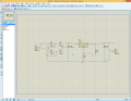
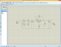
I designed a dc power supply shown in figure 1, and implemented on breadboard. But whenever i turn variable resistor to decrease voltage, after decreasing 7V (approx.), the Variable resistor flashes up (i.e burns down). But as shown in second figure 2, when i place diode D5 at input-output of lm317, the variable resistor doesn't burns up. Can someone please explain me how this diode prevents burning up of variable resistor?
R2 (5K) is the place where i am using variable resistor.
And also can you tell me some points that might could be asked by instructor (because i have viva by tomorrow for this project(i.e after 12 hours approx.))
also i am a beginner, so please try to begin from scratch...
Attachments
-
 87.3 KB Views: 31
 -
 88 KB Views: 32
Last edited:


