Signal voltage problem

strantor

Joined Oct 3, 2010
6,875
So, you are running both the servo and this 12v regulator from the same supply, right?

Then they have a common ground, via the single power supply. Just because you stuck a linear regulator between your single power supply and the servo does not mean that it is isolated. Now, if you had used a 1:1 transformer from the AC to isolate the power, you would have a different situation, and it would be working.
considering he has a separate sig- terminal and 0v terminal on the valve, I assumed that the signal was isolated from the power. I asked and he said he checked that they were not connected internally.
 

SgtWookie

Joined Jul 17, 2007
22,230
A dual regulator would not work, as the supply would have the same source.

Now if you had a transformer that had dual secondaries that were independent, you could then rectify, filter and regulate each secondary and keep them independent, and they would be galvanically isolated from each other.
 

strantor

Joined Oct 3, 2010
6,875
So, you are running both the servo and this 12v regulator from the same supply, right?

Then they have a common ground, via the single power supply. Just because you stuck a linear regulator between your single power supply and the servo does not mean that it is isolated. Now, if you had used a 1:1 transformer from the AC to isolate the power, you would have a different situation, and it would be working.
Wookie you obviously know what you are talking about but I don't. I know I'm not the OP but I have time and interest in this post so can you please explain this for me (and maybe OP if he hasn't already made the leap).

My thinking is that since the signal is isolated in the valve, that no further Isolation would be needed at the source. He's already stated that the signal pins are isolated (basically):

did you test to see if either of the signal pins are connected internally to the 0V pin?
They run into the control board and that's where I lose them. They are not connected directly to 0V.
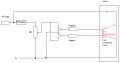
So, basically this is how the drawing should look :


Why would that not work? Why would it matter that the signal is not isolated from the power at the source?

Personally I suspect a wiring fail, because he's stated that there is 20V present on the pot wiper which should never have >12V.
 

Attachments

SgtWookie

Joined Jul 17, 2007
22,230
The servo is being supplied power from the same supply that our OP is powering the 12v regulator with. They omitted that little detail from the schematic, but the two sentences of text I quoted tell the story; it worked fine when they used two supplies that were isolated from each other, but not when they were operating from the same supply. Our OP has stated that they do not know what's in the servo controller, and since we have no photos, schematics, or even a part number, it's hard to guess what might be in there.

The servo input IS high impedance, if the supplies are galvanically isolated - no DC path connecting each other.

The fact that it worked with two isolated supplies, but it did not function properly with a single supply, proves to me that the servo input is not completely high impedance; it may have ESD protection diodes or the like that would not be detected by using a multimeter set to Ohms, but would provide a path for current when applied incorrectly.
 
Last edited:

SgtWookie

Joined Jul 17, 2007
22,230
That isn't a schematic, it's a block diagram.
The Q-CMD comes from a pot that's connected across a +10v/-10V supply, but the source for that supply is not documented.

I don't know where it's getting +24v/0v/+15v/-15v from.
 
Top