 Facebook
 Google
 GitHub
 Linkedin
Hi All,
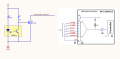
I would appreciate feedback on the proposed circuit for providing the limit switch input to a CoTS motor controller.
Switching Signal should switch high/low when the beam on the KRB031 is either interrupted or not interrupted.
Switching signal will connect to the IN3/LSN signal line of the motor controller.
The input on the motor controller is pulled upto 5V internally. This is why the circuit shown has no pull up itself.
R1 is set @ 220r to give 18mA current on the internal LED which is less than the 25mA max but should provide sufficient illumination.
The motor driver input requires minimum of 3.5V for logic high and maximum 1.6V for logic low.
Have I overlooked anything in the schematic?
Attachments
-
 83.3 KB Views: 11


