Facebook
 Google
 GitHub
 Linkedin


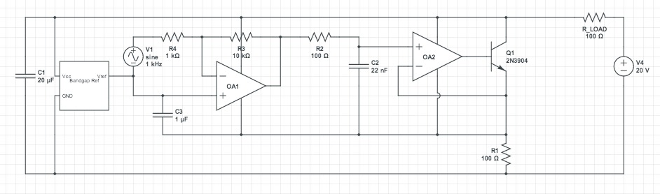
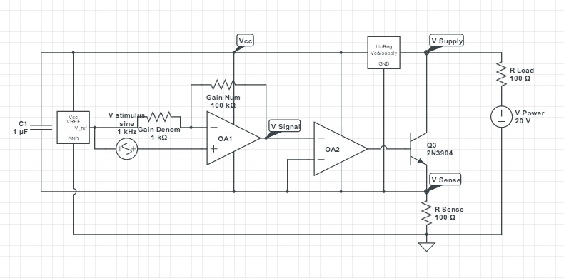
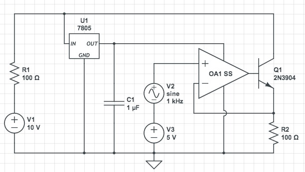
The circuit is a two-wire interface where the voltage across R_LOAD should be proportional to the current drawn by the VCCS plus the DC bias current from the IC Q-currents.
Without the diode isolating the signal terminal from the bypass capacitance, I simply cannot achieve the desired bandwidth due to the effective LPF created by C1 and R_LOAD. The problem is that with the diode, although the VCCS current is not attenuated, it is also not identifiable by measuring the voltage drop across R_LOAD. This is due to the "bias" current fluctuating as the bypass capacitor is charged when the diode is "on" (caused when VCCS draws a minimum current), causing a superposition of these two currents across R_LOAD.
I've hit a snag and hope that there are some suggestions regarding the isolation of the signal path from the large bypass capacitance (C1) necessary for the ICs in this circuit to function properly. Any help is appreciated.