Hello
This thread is related with some problems with AD620 that I explained here,
https://forum.allaboutcircuits.com/threads/ad620-output-diamond-plot-and-some-questions.171686/
but i think this deserves an independent thread.
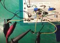
In following pictures ( sorry again for the quality), I measure with a single oscilloscope probe attaching the probe "gound" cable to the circuit ground (i.e,negative power supply cable) as shown with the green color,and attaching to the REF input to amplifier, shown with red color.By mistake, in the red part,i labeled the probe ground bad: the ground goes to REF and the other tip to amplifier output !
Next picture is with the signal generator ground connected to the same ground that oscilloscope and power supply have in common

As you see, i have a constant output voltage if I measure relative to ground, ( green horiz line at scope) but a nice sinusoidal signal of about 2V with 1V on it if i measure against REF(red part)
But if i disconnect the generator from ground, I have this for the same measurement points:

So then i can measure a signal in both points using the green or the red method( with much more noise,by the way)
I do not understand the signal offset in any of the two test, because I would expect a 1Vpp signal on top of a 3V offset.Common mode voltage?Offset from slightly different values in amplifier inputs?
Why in first test I can only measure the signal relative to the REF input?
Maybe then I'm putting a OV virtual ground on AD620 output?
In fact, that seems the way to go,because when measuring with REF as ground the signal is much better...
This thread is related with some problems with AD620 that I explained here,
https://forum.allaboutcircuits.com/threads/ad620-output-diamond-plot-and-some-questions.171686/
but i think this deserves an independent thread.
In following pictures ( sorry again for the quality), I measure with a single oscilloscope probe attaching the probe "gound" cable to the circuit ground (i.e,negative power supply cable) as shown with the green color,and attaching to the REF input to amplifier, shown with red color.By mistake, in the red part,i labeled the probe ground bad: the ground goes to REF and the other tip to amplifier output !
Next picture is with the signal generator ground connected to the same ground that oscilloscope and power supply have in common
As you see, i have a constant output voltage if I measure relative to ground, ( green horiz line at scope) but a nice sinusoidal signal of about 2V with 1V on it if i measure against REF(red part)
But if i disconnect the generator from ground, I have this for the same measurement points:
So then i can measure a signal in both points using the green or the red method( with much more noise,by the way)
I do not understand the signal offset in any of the two test, because I would expect a 1Vpp signal on top of a 3V offset.Common mode voltage?Offset from slightly different values in amplifier inputs?
Why in first test I can only measure the signal relative to the REF input?
Maybe then I'm putting a OV virtual ground on AD620 output?
In fact, that seems the way to go,because when measuring with REF as ground the signal is much better...