Facebook
 Google
 GitHub
 Linkedin

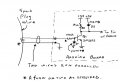
I'm building a tachometer for a small gas engine. I wrapped a solid core wire around the spark plug wire and put a scope on it. I got 3 volts AC RMS (not sure if I'm using the correct terminology, very new at this) with a frequency that made sense for the engine RPM.
My next step is to convert this into a 5 volt DC signal. My idea is:
From the induced voltage wire run a diode and then into the base of a transistor. This transistor would have 5 volts into the collector coming from an Arduino board. The emitter would go to a pin that is monitored in the scan cycle.
Am I headed in the right direction?
Thanks!
My next step is to convert this into a 5 volt DC signal. My idea is:
From the induced voltage wire run a diode and then into the base of a transistor. This transistor would have 5 volts into the collector coming from an Arduino board. The emitter would go to a pin that is monitored in the scan cycle.
Am I headed in the right direction?
Thanks!