 Facebook
 Google
 GitHub
 Linkedin
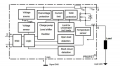
Hey everyone. Hope you are all having a great day. I have the BTS410F High Side Switch in a circuit and looking for a little clearer understanding of how it works. I have attached a diagram and looking for the Coles notes version or laymand terms version of how this works and in particular, what I should be looking for when testing it. Right now, in my circuit, I have 0.0V on pin 1 (GND), 0.0V on pin 2 (IN), which goes to the micro, 13.25V after the main diode on pin 3 (Vbb), 4.95V on pin 4 (ST) which goes to the micro and 0.14V on pin 5 (OUT) which goes to an external pin with no connection to it that I can see.
What should I see for voltages or on a scope that tells me this is working? Does the micro turn it on?
What should I see for voltages or on a scope that tells me this is working? Does the micro turn it on?
Attachments
-
510.9 KB Views: 8
-
 61 KB Views: 8


