Shorts with a negative supply

Thread Starter

relicmarks

Joined Oct 13, 2006
355
you REALLY should build an Octopus.

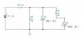
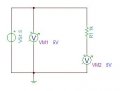
How can a Octopus or Curve Tracer help me with short finding?

I know that a curve tracer or tracker signature are great for component leakage,component shorts but how would they find the SHORTS please?

How would you use a Octopus to find shorts?
 

beenthere

Joined Apr 20, 2004
15,819
It is too bad, but this thread is not really going anywhere. So far, help and advice has been offered, but either ignored or rejected. What is the point of asking questions if you only want to have your own methods verified?

We have replied with a great deal of general guidance. We have yet to hear a positive response, especially when asking about specific problems. As has been suggested, working with a schematic and a good level of understanding about the circuit's functioning is really necessary to be able to troubleshoot.

It would be a good idea if you posted up said schematic and we had some concrete problems to look at.
 

JoeJester

Joined Apr 26, 2005
4,390
relicmarks,

What have you read on the subject of electricity and electronics?

Have you read the ebook here?

Your random inquiries show me that you haven't grasped any understanding of the basics. I suggest you limit your inquiries to something you have read, so you can cite the source. The big bang theory doesn't apply to your learning.

I've decided not to answer any of more of your inquiries till you demonstrate your inquiry deserves attention. You can demonstrate that by following the rules for posting.

I agree with beenthere. I have wasted my time reading and responding to you as your effort has been clearly lacking.

Would you say there was a short if both top and bottom of a resistor measured 5 volts?

YES I would , what would you call it then?
I had asked you this question for a specific reason.

Attached is the model I was implying ... Clearly 1k is not a short.
 

Attachments

JoeJester

Joined Apr 26, 2005
4,390
Since you didn't understand my last question, I broke it down some more.

5 volt source, as you requested. This are no shorts in this circuit. The resistor measures 1k. Why does VM1 and VM2 read 5 volts?
 

Attachments

thingmaker3

Joined May 16, 2005
5,083
Look at the following:

NoShorts.jpg

As with JoeJester's example there are NO SHORTS in the schematic. Yet one of the resistors will always have 5V measured on both sides. When power is applied, point A will read 5V to ground. Depending on switch position, either point B or point C will read 5V to ground, and the other will read 0V to ground.

So, as you see here and in JoeJester's example identical voltage to ground is not an indication of a short.

How does this apply to your own circuit problem? It might not.

How do you get an answer to your circuit problem? Simple: you have to post your schematic, same as Joe and I have done. Without seeing that schematic, no one in the universe can help you!!
 

Thread Starter

relicmarks

Joined Oct 13, 2006
355
thingmaker3:
Depending on switch position, either point B or point C will read 5V to ground, and the other will read 0V to ground.

thingmaker3 , there is no resistor values so how would i know which resistor would read 5 volts to ground and which one would read zero volts to ground ?

JoeJester:
5 volt source, as you requested. This are no shorts in this circuit. The resistor measures 1k. Why does VM1 and VM2 read 5 volts?

a.) Because there is no voltage drop across a 1K or on either side of a 1k resistor?
b.) A voltage multipled by 1 will be the same voltage on both sides?

Whats the real answer?
 

JoeJester

Joined Apr 26, 2005
4,390
You can only have a voltage drop across a resistor, not on either side. Now measuring the voltage drop could be you actually measuring across the resistor or taking two measurements and mentally subtracting them to get the voltage drop.

Your answer a is partially correct.

I don't understand your b) answer at all. Where did the 1 come from?

Let me ask you this ... Is there current flowing through the resistor? If no, why? If yes, why?
 

Thread Starter

relicmarks

Joined Oct 13, 2006
355
C- there is current flowing because it has ground the negative potential hooked up with the positive potential +5 so the electrons can flow from negative to positive

B- I think there is only Voltage on both sides of the resistor, but no current is flowing so there is no voltage drop
 

Thread Starter

relicmarks

Joined Oct 13, 2006
355
a.) Because there is no voltage drop across a 1K or on either side of a 1k resistor?
b.) A voltage multipled by "1K" will be the same voltage on both sides?


I'm guessing that a 1K resistor doesn't change the "current flow rate/value"
to make a voltage drop across it

i think the voltage divider formula for a SINGLE Resistor is

Vin * R1 / R1 = V out

5 volts * 1K/1K= 5 volts

5 volts * 470K/470k= 5 volts

5 volts * 33K/33K= 5 volts

I'm guessing a "Single resistor" with any value "can not" voltage divide?
 

JoeJester

Joined Apr 26, 2005
4,390
relicmarks ... a few things to consider.

In the circuit I presented, there is zero current in the 1k resistor until you attach the meter to the open ended resistor. The meter completes that circuit allowing current flow.

If you had a cheap analog meter with a sensitivity of 5k ohms/V, and the meter scaling was sufficient, you could read 4.167 volts on the open end.

If you had an analog meter of the quality of a simpson 260, it's sensitivity was 20k ohms/volt, and if the meter scaling was sufficient, you would read 4.95 V.

Your DVM has about a 1M or 10M input impedance. It will read 4.995V (1M) and 4.9995V (10M).

You must know the capabilities of your test equipment so when you make a measurement to obtain a reading, you should think about if your loading down the circuit or not.

Some technical documentaton presents the voltages at various points on the schematics. It's important to know what test equipment was used to obtain those readings so if you see different reading, you can know your test equipment is contributing to the error.

Can you tell me your training plan?

What is your path to success, from point "A" to "Z"?
 

Thread Starter

relicmarks

Joined Oct 13, 2006
355
Joe, can you give me some more SHORT finding testing?

Or what have you guys ran into that you thought were shorts but wasn't?

Like what can measure or test like a short but it isn't a short?
 

JoeJester

Joined Apr 26, 2005
4,390
Without a schematic, that indentifies the low impedances, your only guessing. You can either purchase the schematic or draw your own by tracing the circuit.

One example would be the output of an audio amplifier connected directly to a speaker. The DC resistance would be low ohms, yet it isn't a short.

What is your training plan? How are you getting from point "A" to point "B"?
 

Thread Starter

relicmarks

Joined Oct 13, 2006
355
What is your training plan?

In my electronic books, they don't explain must about shorts or how to measure shorts or how to tell the difference between a low resistance reading VS a short and how would i know the difference?


How are you getting from point "A" to point "B"?

By asking questions and reading books
 

Thread Starter

relicmarks

Joined Oct 13, 2006
355
HI guys i found something really cool to find shorts

its called a CURRENT TRACER

1.) Start with the current tracer following the path of current from the source. Continue to follow the expected path of the current. When the tracer comes to the bridge the indicator lamp will probably dim since the current has found some other path to follow.

2.) The current tracer and lare useful in finding low-impedance faults (shorts) in between PCB TRACES.

3.) The majority of the current will pass through the low-impedance fault so the current tracer can be used to trace this path.

4.) Once the current tracer moves past the fault, the lamp indicator on the tracer will dim because the current intensity went down.

5.) This indicates where the majority of the current is going which is most likely the low-impedance fault.

6.) The line may be tied to ground.

7.) Use a function generator set to Squarewaveform must be used to pulse the line in between the gates so there is current for the tracer to follow.


How does this sound guys?
 

Thread Starter

relicmarks

Joined Oct 13, 2006
355
To Test a PCB with alot of ""HIDDENED SHORTS""

1.) Bench power supply, use it as a current source only , turn the voltage down all the way, and turn up the current knob on the power supply to about 100mA or more .

2.) What else can you use as a current source?

3.) Put the current source ( RED probe ) on node#1 input of first stage and the current source ( Black probe) on node#2 of the output of first stage, so it makes a "current loop"

4.) Take your DVM meter and measure the voltages of each node in that faulty stage until you get a low voltage drop reading on a node or pin.

5.) Once you "isolated" the two nodes that get a low voltage drop, put the current source RED probe and Black probe on the two nodes and measure across them to find a voltage drop which will be the "hidden short" inbetween the traces or between the nodes

6.) A short has current flow but NOT a voltage drop

How does this sound ?
 

kubeek

Joined Sep 20, 2005
5,796
It sounds stupid.
EVERY short has some resistance, so it has some voltage drop.
Again, DEFINE WHAT THE HELL IS SHORT!

I think that if you don´t trust you PCB manufacturer, you check them BEFORE you solder any parts in it.
This can be done using the continuity test, becase there are no voltage sources AND there are no components, so these two don´t change your outcomes.


BTW have you ever heard of a thing called Ohms Law? That could help you a lot...
 
Top