Facebook
 Google
 GitHub
 Linkedin
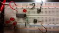
Hello everyone , I have a shift register SIPO HEF4015BD philips and I want to make it work . that means to do he simplest job to enter e.g. a 4 bit word serially and exit it in parallel . I am trying desperately to achieve it ( I connect everything correctly I am sure about that !) for a reason I really do not know , to make the leds lit , the master reset(MR) must be grounded. Can anyone of you lease help me ???
Thank you very much !!
Thank you very much !!