Shielding a battery operated device from electrical fields.

Thread Starter

dannybeckett

Joined Dec 9, 2009
185
Hi guys,

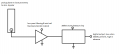
I'm currently developing a receiving device that picks up a specific frequency in your body. A metal strap is used as a pickup, which is in close proximity to the wearers skin. The pickup is connected to an amplifier and a little extra circuitry which detects the presence of the signal. This is also close to the wearers skin. The problem is that the amplifier and extra bits are picking up the signals in the body as much as the pickup is - this is causing common mode signals to appear and hence the device does not detect any signal.

It seems obvious that I need to shield the device for this to work. I need an electrically quiet area from which I can use a reference point, then the only place that the signal can get though is the pickup (as intended). My initial thought was that I would only need to shield the input amplifier but on second thoughts I may need to shield everything - any clarification on what I need to be shielding would be much appreciated.

I also do not know how to properly shield the device. If I put it all in a copper box, where do I connect the copper box to? If I connect it to "ground" (battery negative), then does that not mean all the signal the shield picks up gets put directly into the ground plane? If this is the case, do I leave the shield floating?

As I said I have never had to shield a floating battery operated device before so any pointers, references, criticisms etc. are all very welcome.

Thanks,

Dan
 
Last edited:

Thread Starter

dannybeckett

Joined Dec 9, 2009
185
Hi guys,

Just to add a little clarification on what signals I'm picking up - the person will be holding on to some metal which has a 300kHz sine going through it, at around 1Vpk amplitude - I am not trying to read biological signals with this device (fortunately!), the signal I am trying to obtain is much more 'obvious'. The problem is that it seems like the whole system is susceptible to picking up this waveform, and hence it's not very good at detecting its presence. I just need a way to shield everything that needs to be shielded from this waveform so that I can actually tell whether the signal is present or not.
 
Last edited:

Thread Starter

dannybeckett

Joined Dec 9, 2009
185
Look at this for starters to get some basic background on guarding and shielding.
http://www.analog.com/static/imported-files/application_notes/41727248AN_347.pdf

A fundamental thing to remember is that shielding works by creating a equal and opposite field from the noise/unwanted signal so the energy that would have gone into the circuit is moved elsewhere, it's not destroyed.
Thanks for this - I'll read through this document and see if it sheds any light onto the subject for me
 

Thread Starter

dannybeckett

Joined Dec 9, 2009
185
If the input is just out there in free space it is probably picking up all kinds of "stuff".
Yes, the input will pick up any electrical field in the body. We do have filters in the signal path though, so only the frequency we are interested in propagates through.
 

Thread Starter

dannybeckett

Joined Dec 9, 2009
185
I don't think I can share the whole schematic ronv but I can certainly show you a block diagram. The problem is that the 300kHz is everywhere in the system, not just the pick-up plate. It's a pest!!!
 

Attachments

Kermit2

Joined Feb 5, 2010
4,162
have you tried using a true Earth ground? connecting the metal box with your circuit inside to a short wire that is bonded with a copper rod driven deep into soil? the probe also using a shielded type cable which has its shield tied to the metal box at the exit point?
 

ronv

Joined Nov 12, 2008
3,770
Hmm, well without knowing much about the circuit we can only offer some guesses.
1 volt is not a lot to be radiating. but you might make sure the transmit and receiver wires are shielded with the shield tied to ground.
To test out the theory of noise getting back into the box. Wrap the box in foil and tie the foil to ground.
If your transmit signal is a square wave try to round off the corners making it look more like a sine wave.
 

Thread Starter

dannybeckett

Joined Dec 9, 2009
185
Hi again,

I carried out some experiments yesterday and I'll tell you what happened. I put all the circuitry and battery inside a relatively thick aluminium enclosure, made a very small opening for the pickup plate wire to poke out of and tested whether this had any effect on how well the circuitry picks up the signals. It had no effect whatsoever - I lay the box and plate on the floor, and as I brought my hand toward either the aluminium box or the pickup plate, the device acknowledged the signal. If I brought my hand close to both, it did not acknowledge any (due to the signals entering both the box with the circuitry in it and the pickup at the same time).

I did in fact connect the aluminium box to mains ground, and it did stop the signals penetrating the box. This leads me to believe that for the frequencies we are testing, an aluminium enclosure is wholly ineffective as a faraday cage. I think the solution to this problem is to come up with an electrostatic shield which is effective down to say 100kHz. I have also assumed that it is electrostatic shielding I need and not magnetic (since grounding the aluminium box stopped signals penetrating it, and I don't think the human body emits magnetic fields when charged with a voltage).

Just a little clarification too - the 'transmitter' is simply a sine wave oscillator attached to some metal. It does not radiate 300kHz (very well), it's only when you physically touch the metal the oscillator is connected to, does the field in the body increase to a high enough level for the receiver to detect it (this is how it's designed).
 

Sensacell

Joined Jun 19, 2012
3,432
At 300 khz, your signal is being capacitively coupled, a metal box will be an excellent electrostatic shield for your signal, "poor shielding" is not the problem here.

There must always be a path for return currents, when you put the circuit in the metal box and touch the sensing plate, the return current flows through the capacitance of the metal box to ground. If you now touch the box, the return currents flow through the capacitance between the sensing plate and ground. Grounding the box to the mains ground holds the chassis at a fixed potential, so the box has no signal to return via the sensing plate. What you need to understand is that your signal antenna is not the only component in the system, the ground of your circuit is just as important. When you put your hand near BOTH the box and the sensing plate, there was no differential- both the box (circuit ground) and the plate see the same signal- so no differential for your circuit to detect.
 

Thread Starter

dannybeckett

Joined Dec 9, 2009
185
Thank you very much for this Sensacell. Please let me know if I've grasped what you're trying to say here.

The metal box is blocking electrostatic fields, and it's also capacitively coupled to the circuitry (battery negative/ground) inside. As I come in to proximity (I'm not actually touching any of these components) of the sensing plate, the return currents flow through the box. I would have assumed though, that the quickest path to battery negative (ground) would be through the circuitry alone?

Say I now come into proximity of the box instead of the sensing plate (and the sensing plate is far away from me), I register a signal (which I shouldn't). If this box is acting as a good faraday cage, the 'inside wall' should have no charge on it whatsoever... so how could the ground planes and battery pick up the signal, capacitively or by any other means?

I'm wondering whether the fact the pick-up wires are poking out the side of it unprotected might be an issue - if the box is indeed acting like a faraday cage and shielding the inside from 330kHz, could it be that the wire poking out is picking up the external field changes and bringing in the signal via the pick-up plate line? This would give the impression that the cage isn't working. If this is the case, do you know how I could properly pass the signal wire through the faraday cage?

Sorry if I haven't quite grasped what's going on here, as I said I'm new to this field so it might take a little perseverance.

Thanks again,

Dan
 

BR-549

Joined Sep 22, 2013
4,928
Dan....let me try.
Your body is a relatively non insulated bag of liquid ions. It acts like at capacitor at many frequencies. It can pass ac voltages and signals very easily without even being close to or touching anything. I suggest decreasing the 300 khz amplitude and make it variable. For the young, very little should be needed, for an old pickle like me, you might need a little more. Also....keep the bar short and small. Keep all 300 khz circuitry except bar, heavily shielded.

Not knowing who you are........or what you are doing.........be aware is takes very little voltage and current to kill. Mulimeters have killed.
A sweaty hand with a small cut under a metal ring on a finger can kill also.
 

Sensacell

Joined Jun 19, 2012
3,432
I am guessing here- but if you are trying to detect this small 300 Khz signal that is capacitively coupled to a human body- with a small device that is electrically floating and physically ON the body- you will never detect anything.

For a circuit to detect a signal- a changing voltage level, there must be a flow of electrons through the input- these electrons need a path.

If your sensor box and circuit ground is at the same potential as the signal, there is no signal- think of a bird on a power line.

For the signal to be detected you need a ground, or at least some capacitance to ground, so the signal currents can flow through and be detected.

In the case where you put the circuit and it's power supply in a metal box, then put your hand near it, the signal will couple to the box via stray capacitance, if you connected a scope to the box and ground you would see a signal. The circuitry inside the box is also at the same potential, but there is no path for any current flow, so the circuitry sees no signals. When you put a wire through the wall, now you have created a path for current flow, so you can detect the signal on the box, or the sensing plate, it doesn't matter which, what matters is the flow of current through the input circuit.

Even super high impedance inputs need some current, if only to charge the input capacitance.
 
Last edited:

Thread Starter

dannybeckett

Joined Dec 9, 2009
185
BR-549, Thanks for your input. All of the 300kHz signal generating hardware is physically far away from the person wearing the detection unit, it's the receiving side of things that's causing us the problems. Our experiments did in fact indicate that lower frequencies would be more suited to this application, but for the time being we want to get it working with 300kHz. The signals we're conducting though people are very weak fortunately not much chance of death =]

Sensacell, that's exactly what we're trying to achieve. The problem we're having is exactly how you've described. The return path for the electrons on the pick-up plate will be to the battery negative. The bird on the power line analogy is correct, which is why I'm trying to block the external fields entering the circuitry. What I expected to happen with is that the shield (faraday cage) surrounding the device would block any electrostatic fields getting anywhere near the circuitry we're trying to isolate. I guess this theory is flawed though - even if this box is acting as a faraday cage, is it the case that the cage is capacitively coupling external signals to the board inside? I thought that because the faraday cage keeps net charge on the inside of itself to zero, that it couldn't capacitively couple to the ground plane/battery/everything else inside? Thank you for your perseverance, I am improving my grasp on this problem with each comment.
 
Top