 Facebook
 Google
 GitHub
 Linkedin
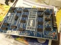
I have a couple 'counter boards' that consists of multiple logic ICs. It's function is to simply count products coming off an industrial machine & reset once the predetermined count is reached.
The input voltage is 15V and output voltage is around 13.5V without a load.
Both boards have the same issue - once a 12V relay is applied, the output drops significantly to 1.9V & will relay will not engage. I have tried putting a 10uf cap in parallel with the output, as well as using a solid state relay to minimize the current draw but no difference.
I am stumped. I am willing to do a modification to the board but not sure where to start.
Any suggestions? (I have attached the schematic, sorry it's scanned)
* The output the relay is connected to is Pin 9 which isn't shown well in the schematic but it is on the far right side of the schematic connected in series with R10 - 39ohms.
Attachments
-
370.6 KB Views: 14
-
 262.3 KB Views: 9


