Facebook
 Google
 GitHub
 Linkedin
Hello all, new user here.
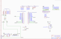
I've recently designed a PCB that is meant to power 6 servos, an rgb led, have 6 DO pins, 6 DI pins, and also power a TFT display. The board will be powered from a bench power supply, an esp32 devkit is the controlling device.
Everything works on a breadboard - and ive ordered a prototype but I'm no electrical engineer. My main reason for posting for a review is to catch any glaring safety concerns that I may be missing as I'd like to design this as well as possible - I'm learning.
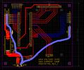
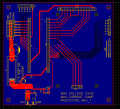
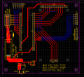
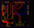
Here's some general information about the board - and I'll include a couple screenshots below.
# Reverse polarity protection - using a mosfet immediately after the VCC terminals to make sure it won't power the board if polarity is not correct.
# 5amp slow blow fuse to allow for brief current spikes on the servo buss - but not allow a continuous current of over 5 amps
# 5mm trace going from mosfet drain to fuse - then to capacitor. mirrored 2.5mm trace with staggered 0.5mm vias to stitch the buss along the servo +vdc pins since the pin spacing wouldn't support a wider trace.
# 1000uf capacitor before servo buss
There is a 100uf capacitor coming off the main buss for the esp32 power, and a couple ceramic capacitors for the led and the esp. The display module has built in capacitors and appropriate hardware so I haven't added any for that. the esp and the display are plug and play on the female headers.
My main concern is it stating it's for 5amps of current - should my traces be sufficient for this on the servo buss? All feedback welcome - thank you guys.
I've recently designed a PCB that is meant to power 6 servos, an rgb led, have 6 DO pins, 6 DI pins, and also power a TFT display. The board will be powered from a bench power supply, an esp32 devkit is the controlling device.
Everything works on a breadboard - and ive ordered a prototype but I'm no electrical engineer. My main reason for posting for a review is to catch any glaring safety concerns that I may be missing as I'd like to design this as well as possible - I'm learning.
Here's some general information about the board - and I'll include a couple screenshots below.
# Reverse polarity protection - using a mosfet immediately after the VCC terminals to make sure it won't power the board if polarity is not correct.
# 5amp slow blow fuse to allow for brief current spikes on the servo buss - but not allow a continuous current of over 5 amps
# 5mm trace going from mosfet drain to fuse - then to capacitor. mirrored 2.5mm trace with staggered 0.5mm vias to stitch the buss along the servo +vdc pins since the pin spacing wouldn't support a wider trace.
# 1000uf capacitor before servo buss
There is a 100uf capacitor coming off the main buss for the esp32 power, and a couple ceramic capacitors for the led and the esp. The display module has built in capacitors and appropriate hardware so I haven't added any for that. the esp and the display are plug and play on the female headers.
My main concern is it stating it's for 5amps of current - should my traces be sufficient for this on the servo buss? All feedback welcome - thank you guys.
Attachments
-
 112.7 KB Views: 8
 -
 211.8 KB Views: 9
 -
 225.5 KB Views: 9