 Facebook
 Google
 GitHub
 Linkedin
Hi Everyone
I am trying to measure a variable resistance(Rv) which changes with input (X) according to the following equation
Rv = 0 Ohm at Xin = 1000
Rv = 1000 kOhm at Xin = 0
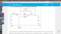
I am using the feedback resistor as 10kOhm. The input resistor is (Rv + 10kOhm). Hence, as per the close loop equation, I should be getting
At Xin = 1000
Vout /Vin = - Rf/Rin = - (10)/(10+0) = -1
with Vin = Vcc = 5V
Vout = -5V (or 5V with phase -180)
At Xin = 0
Vout/Vin = -Rf/Rin = -(10)/(10+1000) = 0
with Vin = Vcc = 5V
Vout = 0 V
I am using LM324 which is a standard Op-Amp and getting 0.6V for Xin = 1000 and 0.0V for Xin = 0.
Please can you let me know if I am doing something wrong.
Aliter
Using a simple voltage divider, between 10kOhm and Rv, I can see the voltage change from 0 - 5 V. The reason for using the OpAmp is to act as an inverter so that Vout ~ Xin rather than it be Vout ~1/Xin.
Best
Chandra
I am trying to measure a variable resistance(Rv) which changes with input (X) according to the following equation
Rv = 0 Ohm at Xin = 1000
Rv = 1000 kOhm at Xin = 0
I am using the feedback resistor as 10kOhm. The input resistor is (Rv + 10kOhm). Hence, as per the close loop equation, I should be getting
At Xin = 1000
Vout /Vin = - Rf/Rin = - (10)/(10+0) = -1
with Vin = Vcc = 5V
Vout = -5V (or 5V with phase -180)
At Xin = 0
Vout/Vin = -Rf/Rin = -(10)/(10+1000) = 0
with Vin = Vcc = 5V
Vout = 0 V
I am using LM324 which is a standard Op-Amp and getting 0.6V for Xin = 1000 and 0.0V for Xin = 0.
Please can you let me know if I am doing something wrong.
Aliter
Using a simple voltage divider, between 10kOhm and Rv, I can see the voltage change from 0 - 5 V. The reason for using the OpAmp is to act as an inverter so that Vout ~ Xin rather than it be Vout ~1/Xin.
Best
Chandra
Attachments
-
 172.4 KB Views: 33


