Hello AAC community,
I am trying to build a PID controlled heater & stuck with the following situation. Any feedback in this regard is appreciated.
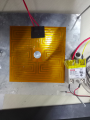
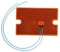
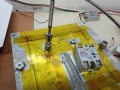
Purpose of the system: Maintaining the set temperature of a heatbed for 1 minute to 99 hours.
Materials:
Problem statement:
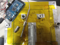
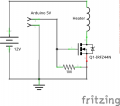
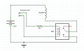
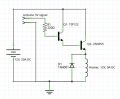
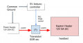
Want to incorporate PID control & PWM for heating. The heater needs 9A continuous current to function properly.
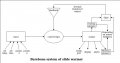
Looking for suggestions regarding selection of proper current controlling components/ system design. (Image attached)
Question 1:
is SSR suitable for this operating PWM frequency.
Question 2:
is 2N3055 suitable for this type of operation where continuous 10A current is drawn for 1minute to 99 hours?
Question 3:
What is the standard practice for designing such applications?
======================
Experiments done:
======================
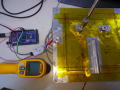
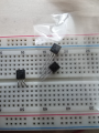
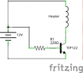
TIP122 (image attached: DSS itr-1.png)
inference: Able to get 5.7 Amps max. which is not sufficient for the heater to function properly in therms of heating time.
SSR AC 40A: Not useful since it cannot make or break the DC contact in the AC terminals. https://www.amazon.in/Robodo-Module-SSR-40DA-3-32VDC-24-380VAC/dp/B07DDKRYPP/
References:
Thank you.
I am trying to build a PID controlled heater & stuck with the following situation. Any feedback in this regard is appreciated.
Purpose of the system: Maintaining the set temperature of a heatbed for 1 minute to 99 hours.
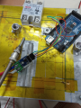
Materials:
- Arduino UNO
- 12V 20A DC supply
- Q1- TIP122
- Q2- 2N3055
- 40A DC Solid State Relay
Problem statement:
Want to incorporate PID control & PWM for heating. The heater needs 9A continuous current to function properly.
Looking for suggestions regarding selection of proper current controlling components/ system design. (Image attached)
Question 1:
is SSR suitable for this operating PWM frequency.
Question 2:
is 2N3055 suitable for this type of operation where continuous 10A current is drawn for 1minute to 99 hours?
Question 3:
What is the standard practice for designing such applications?
======================
Experiments done:
======================
TIP122 (image attached: DSS itr-1.png)
inference: Able to get 5.7 Amps max. which is not sufficient for the heater to function properly in therms of heating time.
SSR AC 40A: Not useful since it cannot make or break the DC contact in the AC terminals. https://www.amazon.in/Robodo-Module-SSR-40DA-3-32VDC-24-380VAC/dp/B07DDKRYPP/
References:
- https://forum.allaboutcircuits.com/...s-in-solenoid-with-arduino-and-2n3055.135084/
- https://forum.allaboutcircuits.com/threads/darlington-pair-10a-12vdc-transistor-spec.7653/
Thank you.
Attachments
-
 31.4 KB Views: 36
 -
 41.4 KB Views: 22
 -
 17.8 KB Views: 24
Last edited:
")