Hello to those far more knowledgeable on the subject of electronics than I.
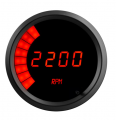
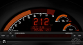
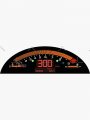
I guess I'll tell you what I'm aiming for and go from there. Ideally, I've been wanting to create a led tachometer that at least resembles the one from a honda s2000, I'll include an image for reference, but to make it a "heads up display". But knowing that it would best function at night and possibly very little during the day, more realistically or perhaps the first thing to do is to learn about how they're made, then trying to make one before I bite off more than I can chew amd become discouraged. Even though this idea or desire, does seem to have some staying power since it keeps popping up in my mind.
I just like the sweeping tachometer that lights up as the rpms increase and maybe some additional lights that light up at a certain rpm, a shift light. I've tried researching online to see if anyone else has made one and if they said how, but have found very little.
The only one I really found was someone who used ten leds in a circle. I thought about just expanding on thier idea, but am unsure of how I would get the resolution that I want. I want one led for every 100 rpm all the way up to 8500 rpm.
I could not illicit a response from them to ask any questions. Like what exactly the computer chip did in that circuit and if it was capable of expanding the number of leds to what I am looking to do. It would go from the ten they used to the 85 that I want to do. Or if that chip was limited to ten leds and I would have to look towards multiplying the same chip or look towards a different chip and if so, which one.
I'm also unsure of how to convert an analog rpm signal to make it work with the leds. Searching online can be a fruitless endeavor when you don't know the correct terms or names of items, that if known would make the search much shorter. But I'm also pretty sure that google just likes to make things difficult for me.
Constantly gives me results that make me feel like I'm getting close to the answers I'm looking for, but never actually giving me the answers I'm looking for. It can drive a person INSANE!!! I'm certain that is thier plan. Create one of the biggest tech companies ever, just to filter my search results in an attempt to slowly drive me insane! Think about it, it's brilliant! Nobody would ever believe me if I said that was thier goal the entire time.... I don't even believe me. Anywa.... What was that?!... the wind.
Anyways, all kidding aside, I guess if I broke it down to the most simple thing that I would like and appreciate some guidance with is to create a tachometer where the analog signal comes in and will sequentially light up leds in 100 rpm increments.
Don't hold it against me if this whole post could have been just the last paragraph. I just wouldn't want anyone to think that I just had an idea, haven't put much thought into how to get it done and want someone who has put a lot of effort into being knowledgeable on the subject to tell me exactly how to do it with as little effort into it as possible on my end. I enjoy learning how to do things and how things work and am willing to put in the work to create something. I think more and more, people seem to take for granted, those who are knowledgeable in the trades, making things work, building things, etc. I am one who appreciates the knowledge and wisdom gained by those who came and did with thier hands before I came around. In fact, I guess you could say I hope to join that fraternity one day. I'm 38 and am knowledgeable in a few different but similar areas, but electronics? Not so much. But I am starting to try and learn.
Thank you for reading my post, if you made it this far, and I appreciate any assistance, advice, guidance and knowledge that anyone is willing to give.
Attachments
-
 44 KB Views: 13