I have an old Sears/Canadian Tire 10a 12v auto battery charger. I’m looking for a schematic for these units. Doesn’t have to be exact, I need to I’d a few components.
Thanks,
Howard
Thanks for reply. Transformer puts out a good 16v, then it goes to the diodes( which are good) and voltage disappears. I’m thinking the circuit board traces maybe bad/ broken.
It's probably a very simple circuit, but we don't know very much about it yet. What components can you see on the circuit board? Does it have an analog current meter?
What DC voltage do you measure on the output of the rectifier bridge?
I remember my dad's first battery charger. A transformer and a finned rectifier with two wires from the transformer to the fins and two more wires coming out of the fins. From there it went to an amp meter then to the battery alligator clips. Plug it in and it was on. Unplug it and it was off. No switches, no boards. Just a simple power source.
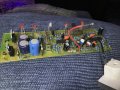
Here is the circuit board. The ac feeds into the lugs by the big blue caps. Not sure what the bent copper wires are used for. The loose wire is just the ammeter dial
OK, that is not at all a simple circuit battery charger! The bent loops of wire are probably resistors used for measuring current. The first thing will be to examine the solder side of the PCB, looking for failed solder connections. Beyond that it will require a circuit schematic to understand what to check. So I would also check the continuity of all the wires to the battery clamps. If they fail the not charge current. AND, some of these chargers require connection to a battery not completely dead to start charging.
What kind of rectifier is this? I know it's a full wave rectifier but there's a name for it. Regardless, my first experience with rectifiers was this sort of rectifier.
And no - I'm not hijacking the thread. I haven't seen one of these in many years. And I don't have one now either.
The charger was hooked to the car battery when my son accidentally started the car. Thought all he blew was the diodes, but actually more was taken out. Caps were replaced. Traces on the reverse side are in poor condition. The transformer puts out a solid 16volts. I’m not giving up on this unit because I’m to stubborn( haha).Hard to find any schematics so maybe I’ll make my own.
What kind of rectifier is this? I know it's a full wave rectifier but there's a name for it. Regardless, my first experience with rectifiers was this sort of rectifier. View attachment 335833
And no - I'm not hijacking the thread. I haven't seen one of these in many years. And I don't have one now either.
Lookomg at the picture of the PCB it looks like the connector on the ammeter is broken off. Without the ammeter in circuit (Or shorted out.) there will be no output from the charger as the ammeter will be in series with the output to the battery connectors. I think something inside the ammeter has melted causing the connector to break off. I agree with MisterBill2 that you will have to trace out the schematic to do any logical fault finding. Just randomly replacing components is a very bad way to fix something.
Lookomg at the picture of the PCB it looks like the connector on the ammeter is broken off. Without the ammeter in circuit (Or shorted out.) there will be no output from the charger as the ammeter will be in series with the output to the battery connectors. I think something inside the ammeter has melted causing the connector to break off. I agree with MisterBill2 that you will have to trace out the schematic to do any logical fault finding. Just randomly replacing components is a very bad way to fix something.
OK, and LES is certainly correct about the ammeter connection! That alone will prevent any charging current flow.
And I can comment on damage caused by starting the car: In any decent battery charger that should not cause any failure!
I do not see any positive output connection on the circuit board, or was that also connected to the ammeter positive terminal.
There must have been something inside the charger that the wires to the battery connectors were connected to. I was assuming that that these went to the PCB and you disconnected them. I spotted two more things when looking at the picture of the board again. One was what looks like a fusible resistor just to the left of the red wire to the ammeter. I can't identify the colour coding on this resistor but I would eaxpect it to have a very low value. You could check that this has not failed open circuit. The other thing I spotted is the item just to the right of the blue 470 uF capacitor, it looks like melted solder. Can you tell us what that is or post a picture talken from the right hand end of the PCB.
Edit. When I wrote this I was replying to post #14 and thinking it was written by Hpilot. So now the first part of this reply does not make any sense.
Les.
Thanks I’ll check out that larger resistor. The other concern of the solder on the bent copper wire/tube was there from new. Not sure why these two copper wires are placed that way or why they are used. Possibly a thermal fuse?
 Facebook
 Google
 GitHub
 Linkedin