Yes, there is. If I disconnect the probe (nothing connected to the BNC input), there's an offset too. If I set the time base to something like 10 or 20 ms (that's already pretty slow), there's still a non-zero mean value.
I updated firmware and did a self callibration successfully. Still, the offset is there.
Could it be a fault? Sometimes is larger, sometimes is lower (same setup).
Today, while working on a real circuit, I got zero offset for a couple of minutes. Then, the offset came back (same circuit, same probe, same attenuation, etc.)
Any idea?
Have you Quick Cal engaged ? It's in the Utilities menu and runs in the background while you use the scope.
It's primary functions are to compensate for the instrument temp as it warms up and adjust for changes in ambient air temperature.
suggestion, If its already been mentioned, then sorry I missed it.
whats the frequency of the signal ?
try DC coupled, Sine wave, direct into scope so no external probe, with a suitable sized external capacitor in series,
Sine wave has equal amplitude + and -, its mean should be zero, its RMS should be calculatable,
May be just pick up of mains in the air on a bit of wire direct into scope on DC is sufficient amplitude to see a good sine wave, and then you would not need a capacitor ,
Just a thought, but does the amount of offset vary with the frequency of the sine wave?
If the “mean” value is computed from a non-integer number of cycles, then would that constitute the “offset”?
in other words, is it at a maximum If the display shows 8 positive half cycles and 7 negative half cycles?
Measurements with a trace offset that cannot be entirely removed can be addressed in a number of ways to obtain better accuracy however do remember that a scopes typical vertical accuracy is just +3%.
Some screenshots for your study, all using RMS and Statistics, first Peak Detect, 2nd 16 Averages and 3rd 3 bits ERES all of which can be selected from the Acquire menu.
SDS1104X-E, 1x probe grabber and reference lead connected to ground, 2mV/div
Out if interest, what size capacitor did you use in the external circuit ?
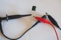
you still have the times 10 engaged, so I am guessing your using the 10:1 probe, can you connect directly , with the capacitor, and send us a picture of the setup .
I see a lot of noise on the peeks of the sine wave, can I suggest slow the sine wave down to something like 100 Hz.
As others have said,
it could be that you are expecting to much from the scope,
Some screenshots for your study, all using RMS and Statistics, first Peak Detect, 2nd 16 Averages and 3rd 3 bits ERES all of which can be selected from the Acquire menu.
SDS1104X-E, 1x probe grabber and reference lead connected to ground, 2mV/div
Out if interest, what size capacitor did you use in the external circuit ?
you still have the times 10 engaged, so I am guessing your using the 10:1 probe, can you connect directly , with the capacitor, and send us a picture of the setup .
I used a 220 nF PET capacitor.
I repeated the same test using 1x probe clipped to one cap lead, the other being clipped by the signal generator (and both ground clips together).
The offset this time is quite benign. If taking the capacitor appart, and connecting probe to sig gen (using AC coupling): The offset is a little bit larger. Still not annoying here.
Problems aries when the RMS value is a few hundreds of microvolts because mean value affects the RMS value (making it larger than it really is). OK, these are quite sensitive measurements.
There're times when offset is on the order of millivolts, and that starts to be a problem. I haven't discovered why the offset value changes between sessions.
Averaging doesn't solve the problem. Anyway it wouldn't be a solution for me, as I'm interested in single events and noise measurements too, which cannot be averaged.
I think as you said, these are very sensitive measurements,
I note you have slowed the sampling speed down now, but its still reporting the same frequency sine wave in , and the results get better.
I also note your sine wave looks terrible, there is an amazing amount of noise on it.
I would also not be surprised if there is not a low frequency on the sine wave as well,
is the mean value constant, or does it vary when your using the external capacitor ,
I'd like to see a picture taken of the setup, as you say this is low voltages, so setup is very critical.
If you want to progress, i think the first thing to do , is improve that sine wave,
you need to remove that high frequency noise that is appearing,.
I'd suggest dropping the frequency down to Hz,
and then using a low pass filter to remove the noise.
as you are now down lower frequency, and the noise should stay the same, it should be a fairly easy passive filter,
again as your down "in the noise" then the setup needs to be good, e.g. filter made on copper clad board.
The noise might come from the signal generator. It is not a great piece of equipment, and the signal is quite low. For larger signal the noise is almost invisible (it powers from a linear supply).
I will try what you said, and will post the results.
I would also not be surprised if there is not a low frequency on the sine wave as well,
is the mean value constant, or does it vary when your using the external capacitor ,
I'd like to see a picture taken of the setup, as you say this is low voltages, so setup is very critical.
I suppose you don't mean a picture of a probe tip attached to its ground clip? (That is what I said in my last post).
Please, tell me what you would like to see, and I will take all pictures that are necessary.
 Facebook
 Google
 GitHub
 Linkedin