'scope newbie: Is it normal to have wiggle in square wave edges?

Thread Starter

cscase

Joined Jan 8, 2015
5
Hi all,
I am a former lurker who just acquired my first oscilloscope. I've done a fair bit of reading and video tutorial watching, and I'm beginning to get comfortable with the scope, but I'm seeing something on mine that I haven't noticed in any videos I've watched, and I just wanted to ask about it. I hope this is not a ridiculous question to ask. I've done a lot of googling and been unable to find much relevant info, but maybe I just don't know the right term to search for.

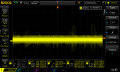
Short version: On a lot of the square waves I look at, the edges (except the one I'm triggering on) flicker and jump left and right between two different positions.

So, I'm wondering if it's one or more of the below:
A) There is something don't understand about how to set up the trigger or other scope parameters to stabilize the waveform
B) The signals I'm probing just have some variance and the scope is accurately representing it, and I shouldn't sweat it
C) It's caused by some kind of external interference
D) There is a problem with my scope or probes
E) It's totally normal and I shouldn't worry about it

Here are some screenshots that show what I am talking about:
DS1Z_QuickPrint5.png DS1Z_QuickPrint6.png DS1Z_QuickPrint8.png

Here are some extra pieces of info:
  • The scope is a Rigol DS1074Z.
  • Signal sources have been various, but the two pictured here are from a pin connected to a two-line LCD display from an Arduino (yellow trace), and a 35 KHz square wave from a Jyetech FG085 signal generator I built from a kit. (http://www.jyetech.com/Products/085/e08503.php)
  • I've tried a lot of the different triggering options and it doesn't seem to make a difference, but I have mostly been using edge triggering on rising edge in about the middle of the amplitude.
  • I also tried fiddling with trigger holdoff, up to the waveform period length, and it didn't seem to affect it the left-right twitching.
  • The probes I'm using came with the scope, and I have them set to 10x.
  • With the signal generator, I tried connecting it different ways:
    • I plugged it straight into a scope input with a BNC cable
    • I plugged it into one side of an unterminated tee connector on an input (because I've seen people doing this online - I don't know why)
    • I tried just hooking onto the signal generator output with the scope probe
  • I've only seen this happening on square waves, not sine or other misc. waveforms I've looked at.
  • It does not do it on the square wave that comes off the metal tab on the front of the scope.
  • If I reduce the frequency from the function generator below 15 or 20 KHz, the effect seems to go away.
Can anyone enlighten me as to what is likely to cause that? Is it typical? When I watch videos online of people setting up triggers on square waves, they always get nice clean edges from what I can see.

Thank you!
 

BillB3857

Joined Feb 28, 2009
2,571
Only a guess, but I would think the scope is showing a variation in the duty cycle of the square wave. Looking at the center picture, I see both rising edges of the first two cycles to be nice and straight, but the fall time of both show variation. The third cycle shows variation of both rise and fall being shaky. Do you have any ripple on the power supply to the signal generator you built? It may not take a lot to have an effect on the output.
 

Thread Starter

cscase

Joined Jan 8, 2015
5
Only a guess, but I would think the scope is showing a variation in the duty cycle of the square wave. Looking at the center picture, I see both rising edges of the first two cycles to be nice and straight, but the fall time of both show variation. The third cycle shows variation of both rise and fall being shaky. Do you have any ripple on the power supply to the signal generator you built? It may not take a lot to have an effect on the output.
Thanks, Bill! I will check this as soon as I get home. Come to think of it, I think I used the same AC adapter to power both the Arduino and the signal generator I was checking these from. Maybe a connection there? I will check its output for ripple, and also try a different power source altogether to see if it changes anything. Thank you for taking your time to help me!
 

ErnieM

Joined Apr 24, 2011
8,377
Try putting your probe onto the CAL output on the front of your scope. That should be a very stable square wave.

If so, your scope is good and the signals be wiggley.

If not so, your scope is wiggley and you don't know 'bout nuthin' else.
 

Thread Starter

cscase

Joined Jan 8, 2015
5
I checked the power supply to the signal generator. It is an AC adapter of the sort you can power an Arduino with. I didn't find any ripple on it to speak of, but I then tried a different AC adapter, just as a troubleshooting step and found everything was the same with both of them.

The CAL output on the front of the scope does indeed put out a nice clean square wave.

When I first noticed this on the signal generator, I figured maybe it's just because it's just a kit build thing to tinker with, maybe it's rinky dink, so no big deal, but then when I saw that happening in other places I wondered if I had a problem.

So it sounds like the overall consensus is... "Not sure what is causing the wiggle, but it's probably not the scope itself"?

Maybe I just need to look at more signals from different sources and get a broader sample base, see if it happens a lot? I'm trying to think of some different places where I might find a good square wave to look at.

Thanks Bill, #12, and Ernie for your help and thoughts!
 

BillB3857

Joined Feb 28, 2009
2,571
Out of curiosity, how did you check for ripple? Scope to AC coupling, V scale to .05V/div? Check TP12, TP13 and TP17 on your signal generator.
 

joeyd999

Joined Jun 6, 2011
5,285
Definitely jitter on the incoming waveform. Looks like it is a software generated square wave, where the jitter is caused by an instruction cycle or so worth of uncertainty.
 

BillB3857

Joined Feb 28, 2009
2,571
Just noticed something else.... Set your signal generator to 20 or 40 Khz. 35Khz is not an even division from the 20Mhz clock in your signal gen.
 

BillB3857

Joined Feb 28, 2009
2,571
I just did an experiment.. I have a function gen similar to but not exactly like yours. Although not as pronounced as what you are seeing, I see something very similar on my Techtronix scope. Just changing the output frequency by a few hundred cycles cause the problem to be greater or lesser. I think all posters have come to an agreement that it is the output of your signal generator and not your scope that is cause and probably a result of the countdown process from the 20 Mhz.
 

Thread Starter

cscase

Joined Jan 8, 2015
5
I just did an experiment.. I have a function gen similar to but not exactly like yours. Although not as pronounced as what you are seeing, I see something very similar on my Techtronix scope. Just changing the output frequency by a few hundred cycles cause the problem to be greater or lesser. I think all posters have come to an agreement that it is the output of your signal generator and not your scope that is cause and probably a result of the countdown process from the 20 Mhz.
Thanks so much, Bill. And joey and nsaspook as well.

When I went to check for ripple, I set it to AC coupling and then just sort of fiddled around, zooming in and out on both axes. Here's what I saw:
DS1Z_QuickPrint16.png

I figured it was alright, no? I see no resemblance:
red1.jpg

I also probed the test points on the board in the FG. I found the output signal at a couple of spots. One was near the output BNC plug, and another was near an Atmel chip closer to the middle of the board. But in both cases, it still looked the same with the "wiggle."

I set it to 20 KHz and 40 and also just scanned up and down a bit, checking in 500Hz increments. Like you, I saw that the effect is worse at some frequencies than others.

I was thinking, if this case of the twitching edge is just the source, what about the other signals where I saw it on edges in a signal from my Arduino? So, I found the signal in question again, and it was still doing something similar, but this time, having done a lot of fiddling with the trigger settings while troubleshooting the FG, I was able to mess around and get it to lock in nice and solid. So, seems like case closed!

Thanks again, Bill and everybody, for your help in figuring out what is going on here and for giving of your time to teach me.
 

Attachments

BillB3857

Joined Feb 28, 2009
2,571
Lower your time base so that you can look for 60 or 120Hz ripple. ( Maybe 50 or 100 Hz ripple since I don't know where you live in the world.) Your scope time base is set at a point that would be impossible to see line frequency ripple.
 

Thread Starter

cscase

Joined Jan 8, 2015
5
Lower your time base so that you can look for 60 or 120Hz ripple. ( Maybe 50 or 100 Hz ripple since I don't know where you live in the world.) Your scope time base is set at a point that would be impossible to see line frequency ripple.
Aha, okay. I checked it again, this time at 50 mV and the lowest timebase possible, and I DO see a regular waveform here among all the noise. So, does this show that there is about 25 mV of ripple on there?
DS1Z_QuickPrint17.png
 

BillB3857

Joined Feb 28, 2009
2,571
I may be reading it wrong, but do you have your horizontal sweep at 5nS.? I should have said "slow down your time base." Try setting it for something like 5 milliseconds. 60Hz ripple would be 16.7 milliseconds/cycle and 50Hz ripple would be 20 milliseconds/cycle.
 
Last edited:
Top