Scooter controller help

Thread Starter

stevon

Joined Apr 22, 2020
38
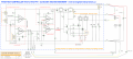
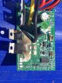
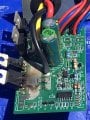
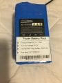
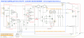
I was wondering if anybody can help in using this controller DC10-55V 60A PWM or another design to run a DC motor (my1020D) 24 volt, 500 watts. I want to control speed with throttle on a toy ATV that I changed the motor on. The original 13amp (YIYUN YK1912K) controller burned up. I then bought a YIYUN YK31C then the motor smoked (MY1016). So lately the controller smoked again. I don't want to buy controllers like a weekly bagel purchase. Lord there has to be a better way! Have been looking online for controller projects, and I studied Electrical engineering after high school so I am savy with electronics and circuit fabrication.
 

Attachments

Thread Starter

stevon

Joined Apr 22, 2020
38
My design requires:
24 volt lithium battery, LION 25.2 V, 7.8Ah 18650 cells with built in BMS (I have this already)
24 volt 500 Watt DC motor MY1020D (I have this already)
A max current limited to 27 amps listed on motor (maybe that's peak and only for a few seconds?)
variable speed control (throttle on ATV)
prevention of burning up battery, motor or controller
Is this too much to ask without buying an expensive Curtis golf cart controller?
YIYUN YK31C controller is the burnt one pictured
 

Alec_t

Joined Sep 17, 2013
14,313
A max current limited to 27 amps listed on motor (maybe that's peak and only for a few seconds?)
I wouldn't rely on that figure. DC motor starting current is generally several times the rated running current.
A nominally 500W 24V motor should be pulling around 20A under very light load, so it wouldn't be surprising to have a starting/stalled current of ~80A. Hence I'd be looking for a speed controller able to handle at least 100A.
 

MisterBill2

Joined Jan 23, 2018
18,463
You have a 500 watt motor and a battery that may not be able to handle that load very long, leading to a possible voltage droop that may cause controller problems. I see no heat sinks on the two transistors in the picture of the motor controller and certainly heat will cause lots of problems. A motor driving any sort of vehicle is subject to varying loads, and since that is a very high duty cycle application heat will certainly be a big problem.
OR did you remove the heat sink for the photo??
 

Thread Starter

stevon

Joined Apr 22, 2020
38
MisterBill2,

The removed case was the heatsink, the whole ribbed aluminum box. So I need a bigger battery?

You have a 500 watt motor and a battery that may not be able to handle that load very long, leading to a possible voltage droop that may cause controller problems. I see no heat sinks on the two transistors in the picture of the motor controller and certainly heat will cause lots of problems. A motor driving any sort of vehicle is subject to varying loads, and since that is a very high duty cycle application heat will certainly be a big problem.
OR did you remove the heat sink for the photo??
 

Attachments

Thread Starter

stevon

Joined Apr 22, 2020
38
Alec_t

You have a good point but 100 amps that would destroy/disable the battery pack (BMS inside). Also the motor cannot sustain a 100 amp supply for very long. soft start controller? Tapering power?
What I need is probably a current limit control because these cheap Taiwan ones don't and a way to make sure feedback from the motor when still turning (momentum) after power is stopped from the controller upsets the Mosfets/ burns them up

I wouldn't rely on that figure. DC motor starting current is generally several times the rated running current.
A nominally 500W 24V motor should be pulling around 20A under very light load, so it wouldn't be surprising to have a starting/stalled current of ~80A. Hence I'd be looking for a speed controller able to handle at least 100A.
 
Last edited:

MisterBill2

Joined Jan 23, 2018
18,463
Motor wattage is given for operation at some rated torque and RPM. Amps=watts/volts=500/24=20.83 amps. But 500 watts is about 3/4 horsepower and that will not move a 4-wheeler like the one in the photo very fast. Do you have access to an ammeter in the 100 amp range? Even a 10% accuracy one will tell if the problem is a major motor overload. The problem with series DC motors, and PM DC motors is that they will make power no matter what the load. So they will burn up at large torque if stalled.
My suggestion is to read the specifications for some similar 4-wheelers and see what they give as motor power ratings. That will let you know a lot more about what size motor you need for whatever performance level you want, and those numbers will not be guesses.
 

Thread Starter

stevon

Joined Apr 22, 2020
38
MisterBill2,

The controller and motor upgrade have worked great for 3 months now until the YK31C burnt recently. For under $400 total for vehicle and upgrades, really can't complain but it is tedious constantly replacing parts. With a little planning and a component I beleive I can save myself a lot of headaches, I'm not alone hundreds of scooter owners around the world are having similar regular failures.
 

Thread Starter

stevon

Joined Apr 22, 2020
38
MisterBill2

The problem with most of these mini ATVs is that they are not capable of carrying anything over the weight of a parrot! The speed is 10 mph and safe for my tiny yard. Speed was never the problem.
The upgrade was necessary for the 50 lb load (girl) who this Item was purchased for. The sellers of this device said it was rated at 120lbs but it never could carry that load. At 50 lbs load controller failed with a total of 3 rides and 2 hours total use time. Upgrading to YK31C controller added more power but the motor started smoking. Upgrading motor worked for 3 months daily use (90 or so hours) but now the controller burned up. I don't know how to permanently fix this without spending $2K or so. I'm handy and somewhat clever with electronic projects.

Original AD:

Kid Size ATV Electric ATV Mini Quad ATVs 4 Wheeler 350W Ride On ATVs


Specifications​

Capacities / Dimensions
Frame /Body/ Suspension / Brakes
Engine/Drive Train
Motor Power350W 24V (Brush Motor)
Final DriveChain Drive
ReverseNo
Start SystemElectric
Max Speed (MPH)10mph (Depending on Riders Weight and Road Conditions)
Max Distance Range15km
Charge Time3.5 hours
Riding Time50 minutes
Battery25.2V/7.8Ah lithium battery
Front BrakesNo
Rear BrakesMechanical Disc Brake
Front Tires4.10-6"
Rear Tires13*5.0-6"
Load Capacity (lbs)120
Net Weight (lbs)57
Gross Weight (lbs)66
Overall Length38.2"
Overall Width21.2"
Overall Height25.6"
Carton dimension (L*W*H/in)36.5" x 21" x 16"
Wheelbase26.4"
Seat Height16.9"
Min Ground Clearance2.4"
Handle Bar20.9"
Handle Bar Height22.8"
Battery IndicatorYes

Stephen

Motor wattage is given for operation at some rated torque and RPM. Amps=watts/volts=500/24=20.83 amps. But 500 watts is about 3/4 horsepower and that will not move a 4-wheeler like the one in the photo very fast. Do you have access to an ammeter in the 100 amp range? Even a 10% accuracy one will tell if the problem is a major motor overload. The problem with series DC motors, and PM DC motors is that they will make power no matter what the load. So they will burn up at large torque if stalled.
My suggestion is to read the specifications for some similar 4-wheelers and see what they give as motor power ratings. That will let you know a lot more about what size motor you need for whatever performance level you want, and those numbers will not be guesses.
 

Attachments

Last edited:

dendad

Joined Feb 20, 2016
4,476
At the very least, I'd add a l suitably rated Tranzorb across the board supply to clip the spikes. Then, install the extra optional FET.
It looks like the circuit has current limiting, but to what that is set I do not know. You may be able to set it to a lower value by reducing "R14+R15+R34+R35". Or increasing the "L1 L2" value.
Make the current limit quite a bit lower to ensure it is working.

Also, add a layer of solder to those bare tracks to the FETs. They are left without the solder mask so that can be done to increase the current carrying capacity. Often I see boards that do not have the solder added that the designer allowed for. (Mine included).

years ago, I designed a similar speed controller for an electric bike. My workmate has great fun holding the bike's brakes on and winding up the speed control until it smoked.
Finally, I got the current limit set correctly so it survived. The motor should accelerate smoothly under full throttle with the current limit operating until the max speed is reached. Not smoke ;)
 

Thread Starter

stevon

Joined Apr 22, 2020
38
dendad,

A non smoker likes your ideas, lol. Thank you for your suggestions, do you have a part number for a Tranzorb and comment "across the board supply" you mean the battery connection or the motor connection? also I would like to see your design if it it isn't proprietary.
part like: 100 Vishay Gen. Semi. P6KE30C-E3/1 28.5V TranZorb Transient Voltage Suppressors

Stephen

At the very least, I'd add a l suitably rated Tranzorb across the board supply to clip the spikes. Then, install the extra optional FET.
It looks like the circuit has current limiting, but to what that is set I do not know. You may be able to set it to a lower value by reducing "R14+R15+R34+R35". Or increasing the "L1 L2" value.
Make the current limit quite a bit lower to ensure it is working.

Also, add a layer of solder to those bare tracks to the FETs. They are left without the solder mask so that can be done to increase the current carrying capacity. Often I see boards that do not have the solder added that the designer allowed for. (Mine included).

years ago, I designed a similar speed controller for an electric bike. My workmate has great fun holding the bike's brakes on and winding up the speed control until it smoked.
Finally, I got the current limit set correctly so it survived. The motor should accelerate smoothly under full throttle with the current limit operating until the max speed is reached. Not smoke ;)
 
Last edited:

dendad

Joined Feb 20, 2016
4,476
https://www.digikey.com.au/product-...l-co/1-5KE33CA-TP/1-5KE33CA-TPMSCT-ND/1960017
Cathode (stripe) to +ve. (Vcc) and Anode to the GND terminal.
As for the design, that was probably 20+ years ago, and I doubt I could find it.
I do remember the bike we did originally has 2 x 12V car batteries, and the "controller" it came with started on 12V, then switched to 24V. It would try to toss you off it if you started full on 24V.
Our controller just sped up smoothly. The guy complained that it did not work as well, no longer this wild start, but in his testing up a local hill, with ours, the bike managed to climb the hill a couple more times from full charge than his switch version. So, the smooth takeoff was way more efficient. Max speed was the same.
 

Thread Starter

stevon

Joined Apr 22, 2020
38
dendad,

I saw an interesting article by David Spilka, Czechoslovakian? he had some interesting points about this controller:

http://film.datriware.com/YK31C_mod_tuning

I also ordered 2 pcs of NTE2996 Mosfets to replace the burned up ones:

Absolute Maximum Ratings:
Drain Current, ID
Continuous (VGS = 10V)
TC = +25C (Note 1) . . . . . . . . . . . . . . . . . . . . . . . . . . . . . . . . . . . . . . . . . . . . . . . . . . . . . . . 84A
TC = +100C . . . . . . . . . . . . . . . . . . . . . . . . . . . . . . . . . . . . . . . . . . . . . . . . . . . . . . . . . . . . . . 59A
Pulsed (Note 2) . . . . . . . . . . . . . . . . . . . . . . . . . . . . . . . . . . . . . . . . . . . . . . . . . . . . . . . . . . . . . 330A
Total Power Dissipation (TC = +25C), PD . . . . . . . . . . . . . . . . . . . . . . . . . . . . . . . . . . . . . . . . . . . 200W
Derate Above 25C . . . . . . . . . . . . . . . . . . . . . . . . . . . . . . . . . . . . . . . . . . . . . . . . . . . . . . . 1.4W/C
Gate−Source Voltage, VGS . . . . . . . . . . . . . . . . . . . . . . . . . . . . . . . . . . . . . . . . . . . . . . . . . . . . . . . . . 20V
Single Pulsed Avalanche Energy (IAS = 50A, L = 260H, Note 3), EAS . . . . . . . . . . . . . . . . . . 320mJ
Avalanche Current (Note 2), IAR . . . . . . . . . . . . . . . . . . . . . . . . . . . . . . . . . . . . . . . . . . . . . . . . . . . . . . 50A
Repetitive Avalanche Energy (Note 2), EAR . . . . . . . . . . . . . . . . . . . . . . . . . . . . . . . . . . . . . . . . . . 17mJ
Peak Diode Recovery dv/dt (Note 4), dv/dt . . . . . . . . . . . . . . . . . . . . . . . . . . . . . . . . . . . . . . . . . . 4.0V/ns
Operating Junction Temperature Range, TJ . . . . . . . . . . . . . . . . . . . . . . . . . . . . . . . . . . −55 to +175C
Storage Temperature Range, Tstg . . . . . . . . . . . . . . . . . . . . . . . . . . . . . . . . . . . . . . . . . . −55 to +175C
Maximum Lead Temperature (During Soldering, 1.6mm from case, 10sec), TL . . . . . . . . . . +300C
Maximum Thermal Resistance:
Junction−to−Case, RthJC . . . . . . . . . . . . . . . . . . . . . . . . . . . . . . . . . . . . . . . . . . . . . . . . . 0.75C/W
Junction−to−Ambient, RthJA . . . . . . . . . . . . . . . . . . . . . . . . . . . . . . . . . . . . . . . . . . . . . . . . 62C/W
Typical Thermal Resistance, Case−to−Sink (Flat, greased surface), RthCS . . . . . . . . . . . . 0.50C/W
Note 1. Calculated continuous current based on maximum allowable junction temperature. Package
limitation current is 75A.
Note 2. Repetitive Rating: Pulse width limited by maximum junction temperature.
Note 3. This is a calculated value limited to TJ = +175C.
Note 4. Isd < 50A, di/dt <230A/s, VDD < V(BR)DSS, TJ < +175C

Stephen
 

dendad

Joined Feb 20, 2016
4,476
I can add a mosfet to this board, T5 has component holes but it is not filled in this application.
Yes, indeed.
You can check the current limiting is working while running the motor on no load, then lower the current limiting ref volts with a resistor to see if the motor slows.

Can you please post a clear picture of the top and the bottom of the board as I'm trying to validate the circuit. There are some problems with it as shown.
EDIT: I have found a few more pictures, but a hi res one would help.
 
Last edited:

MisterBill2

Joined Jan 23, 2018
18,463
MisterBill2

The problem with most of these mini ATVs is that they are not capable of carrying anything over the weight of a parrot! The speed is 10 mph and safe for my tiny yard. Speed was never the problem.
The upgrade was necessary for the 50 lb load (girl) who this Item was purchased for. The sellers of this device said it was rated at 120lbs but it never could carry that load. At 50 lbs load controller failed with a total of 3 rides and 2 hours total use time. Upgrading to YK31C controller added more power but the motor started smoking. Upgrading motor worked for 3 months daily use (90 or so hours) but now the controller burned up. I don't know how to permanently fix this without spending $2K or so. I'm handy and somewhat clever with electronic projects.

Original AD:

Kid Size ATV Electric ATV Mini Quad ATVs 4 Wheeler 350W Ride On ATVs


Specifications​

Engine/Drive Train
Frame /Body/ Suspension / Brakes
Capacities / Dimensions
Motor Power350W 24V (Brush Motor)
Final DriveChain Drive
ReverseNo
Start SystemElectric
Max Speed (MPH)10mph (Depending on Riders Weight and Road Conditions)
Max Distance Range15km
Charge Time3.5 hours
Riding Time50 minutes
Battery25.2V/7.8Ah lithium battery
Front BrakesNo
Rear BrakesMechanical Disc Brake
Front Tires4.10-6"
Rear Tires13*5.0-6"
Load Capacity (lbs)120
Net Weight (lbs)57
Gross Weight (lbs)66
Overall Length38.2"
Overall Width21.2"
Overall Height25.6"
Carton dimension (L*W*H/in)36.5" x 21" x 16"
Wheelbase26.4"
Seat Height16.9"
Min Ground Clearance2.4"
Handle Bar20.9"
Handle Bar Height22.8"
Battery IndicatorYes
Stephen
OK, I was not certain that it was a kid's 4 wheeler. But the specifications now point to another non-electrical possibility, which is the disk brake. If that somehow sticks then certainly the load will be a lot greater. And since I have been bothered by sticking disk brakes many times on many vehicles I suggest investigating that possibility.
And I did not realize that the person in the picture was not the TS. I do not make presumptions about people based on their appearance. She could be a petite 15 year old genius writing here.
My 5 year old nephew has a tractor of a similar class , but it has two lead/acid gell cells and a High/low speed selector and the "go" pedal is a switch.
One option with your vehicle could be a switch engaged near full speed that bypasses the speed controller and provides a direct battery connection. That would allow smooth starts and slightly faster speeds and totally bypass the controller for the higher current operation. That might not even require a relay yo do the switching, unless the electrical part of the control is in the handlebars. Or is that a push/pull cable operating a variable resistor inside the unit?
 

dendad

Joined Feb 20, 2016
4,476
Check the resisters, R2 and R3, they may have been damaged.
When you run this, use a 24V headlight lamp, or just a couple of 12V lamps in series, in place of the motor. That will help limit the current.
 

dendad

Joined Feb 20, 2016
4,476
Measure "L2" and it should show a short as it is 0.002ohms.
Also, see what voltage is across R14 or R15. Then you can work out what current the thing will limit at by using that voltage /0.002 as L2 is the current sensing resistor.
To lower the max current, add a resistor on top of R14 or R15.

On the circuit shown, D2 looks to be reversed.

EDIT: Ah! My printout had the brake line too faint to see.
So D2 is ok. I thought the current limit lit the BRAKE LED, but the brake switch grounds the line via D2.

And the brake light must not just be an LED, but include a current limiting resistor. A 2K2 resistor will be ok.
The same applies to the "LIGHT" LED.

It may be worth checking Q1 and Q2 as well.
Do you have an oscilloscope?
But if you can control the test lamp brightness, then I reckon the transistors will be ok.
 
Last edited:
Top