Schmitt Triggers to LM386 Question (Volume Issues)

Thread Starter

drmanmachine

Joined Mar 12, 2016
68
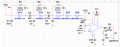
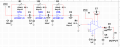
I am working on three synced oscillators by outputting it to an LM386 for amplification. My only concern is that the 10k pot that I use on the non-inverting input of the LM386 appears to be affecting the frequency of the oscillator and also not performing as expected when it comes to volume control. I'm not sure if it's the type of 10k pot I am using or if I need to be using a different component on the circuit. I posted a schematic that I pieced together in Multisim. Disregard the 5V on the Schmitt Triggers since the ones I am using on breadboards can handle a 9V input.

Can anyone point out what I can do to ensure that the volume has a linear response?
 

Attachments

Bordodynov

Joined May 20, 2015
3,430
Add a resistor between the output of the Schmitt trigger and the potentiometer. This will reduce the magnitude of the signal and reduce the load of the logic gate. Take a resistor of 100 kΩ or more.
 

AnalogKid

Joined Aug 1, 2013
12,043
Why is Vcc tied directly to the input of the first stage?

The output of the oscillator part of the circuit is a 9 V p-p square wave. That is more than an LM386 can make at it's output no matter what the gain. You have the gain set at 200, which means that an input of only 35 mV will drive the amp to saturation, and any input increase above that will be unseen. Delete C7 to reduce the gain, put a 100 K resistor between C6 and the top of R4, and see if that gives you some control.

ak
 

Thread Starter

drmanmachine

Joined Mar 12, 2016
68
Why is Vcc tied directly to the input of the first stage?

The output of the oscillator part of the circuit is a 9 V p-p square wave. That is more than an LM386 can make at it's output no matter what the gain. You have the gain set at 200, which means that an input of only 35 mV will drive the amp to saturation, and any input increase above that will be unseen. Delete C7 to reduce the gain, put a 100 K resistor between C6 and the top of R4, and see if that gives you some control.

ak
I took away C7 and put a 100k between C6 and the top of R4. It's a little better, but as I adjust the pot, I can hear the oscillator frequency changing as well. Also, when the sound is at minimum, I am still detecting noise from the speaker.
 

Thread Starter

drmanmachine

Joined Mar 12, 2016
68
Add a resistor between the output of the Schmitt trigger and the potentiometer. This will reduce the magnitude of the signal and reduce the load of the logic gate. Take a resistor of 100 kΩ or more.
I used a 100k and a 1uF in series, but still could not get a good result.
 

Thread Starter

drmanmachine

Joined Mar 12, 2016
68
The unused inputs of a CMOS IC should never be left floating, since that can cause the IC to malfunction.
I understand. I went ahead and grounded the unused pins. With that said, I ended up using a 100uF to filter any unwanted noise across the power supply. It appeared to have made the necessary adjustments to help improve my volume control stage of my circuit, thus allowing me to move forward to the actual building of my sound machine. Thank you for all of your input.
 
Top