 Facebook
 Google
 GitHub
 Linkedin
Greetings!
I am brand new - as in, never built a circuit of my own ever - to electronics but so far I am incredibly excited to be taking on my current challenge. I am working on building a Word Clock partly because I find them to be incredibly cool, but also because they only appear to be of moderate difficulty and help to introduce me to both: circuit design (optional I guess) and microprocessors.
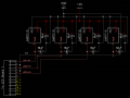
Having said that, I am using diptrace to construct a schematic for power distribution at the moment. I realize that what I've uploaded isn't much of a circuit yet but it's the foundation from which most things in my circuit will run and for that reason, I would really appreciate anyone that could look it over and make sure (primarily) that +5v will in fact arrive on the jumper pads as planned.
The "LED Board" (of which there will be four) is another PCB that I will build that will each house an 8x8 LED matrix, for a 16x16 matrix in the end. I do realize that each LED board having it's own voltage regulator is probably overkill but I happen to have them and I think this will greatly reduce any heat concerns. I also just realized while typing this that I am short one regulator on the board since there are four LED boards and I need to power the main board (Atmega328, DS3231 RTC, etc.).
Anyway, constructive criticism would be greatly appreciated.
I am brand new - as in, never built a circuit of my own ever - to electronics but so far I am incredibly excited to be taking on my current challenge. I am working on building a Word Clock partly because I find them to be incredibly cool, but also because they only appear to be of moderate difficulty and help to introduce me to both: circuit design (optional I guess) and microprocessors.
Having said that, I am using diptrace to construct a schematic for power distribution at the moment. I realize that what I've uploaded isn't much of a circuit yet but it's the foundation from which most things in my circuit will run and for that reason, I would really appreciate anyone that could look it over and make sure (primarily) that +5v will in fact arrive on the jumper pads as planned.
The "LED Board" (of which there will be four) is another PCB that I will build that will each house an 8x8 LED matrix, for a 16x16 matrix in the end. I do realize that each LED board having it's own voltage regulator is probably overkill but I happen to have them and I think this will greatly reduce any heat concerns. I also just realized while typing this that I am short one regulator on the board since there are four LED boards and I need to power the main board (Atmega328, DS3231 RTC, etc.).
Anyway, constructive criticism would be greatly appreciated.
Attachments
-
 34.5 KB Views: 51


