 Facebook
 Google
 GitHub
 Linkedin
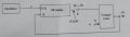
8 bit programmable frequency divider with upward counting and comparator circuit.
Only hct/hc ic allowed. The oscilator should provide two clock signals with the freq (1) 5.7HZ
and (2) 540 kHZ and also a bistable mode (to manual control the clock signal)
I only designed the block diagram, I need your help now to design the schematic!!!
Only hct/hc ic allowed. The oscilator should provide two clock signals with the freq (1) 5.7HZ
and (2) 540 kHZ and also a bistable mode (to manual control the clock signal)
I only designed the block diagram, I need your help now to design the schematic!!!
Attachments
-
 49.3 KB Views: 20
.png")


