Facebook
 Google
 GitHub
 Linkedin
I am running LTSpice Ver 24.0.9.
I have created a circuit symbol for an inverter based upon a pair of complementary of PMOS and NMOS FET's.
The generating circuit is shown as the attachment, "Inverter Circuit_4".
The model based upon this MOSFET pair is shown in the attachment, "inverter.asy".
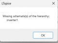
I have changed the symbol drawing to "cell" and have tried to save it to an LTSpice library so that I can bring it up and place it into a circuit that I am working on.
I continue to fail.
Where/how should I save this symbol so that when I hit the components icon, I can see the name "inverter" in this library, and when selected, this inverter model would come up, much the same as when I select "nmos" for example? Then I can place "inverter" into my LTSpice circuit model.
Or, should I save this model elsewhere into another LTSpice parts file to use it an LTSpice circuit model?
I have created a circuit symbol for an inverter based upon a pair of complementary of PMOS and NMOS FET's.
The generating circuit is shown as the attachment, "Inverter Circuit_4".
The model based upon this MOSFET pair is shown in the attachment, "inverter.asy".
I have changed the symbol drawing to "cell" and have tried to save it to an LTSpice library so that I can bring it up and place it into a circuit that I am working on.
I continue to fail.
Where/how should I save this symbol so that when I hit the components icon, I can see the name "inverter" in this library, and when selected, this inverter model would come up, much the same as when I select "nmos" for example? Then I can place "inverter" into my LTSpice circuit model.
Or, should I save this model elsewhere into another LTSpice parts file to use it an LTSpice circuit model?
Attachments
-
416 bytes Views: 2
-
559 bytes Views: 2