Facebook
 Google
 GitHub
 Linkedin
I am attempting to construct a power supply that will allow me to power my old Galaxy S7 without a battery. I created a thread on the XDA forums since it was cellphone related, but now I realize that my question has become too specific to electronics for that forum, which is mostly focused on software. If you would like to know more reasoning/background on my project, please refer to that thread, I will try to keep my copy/pastes as concise as I can.
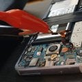
Here are the pictures from the disassembled phone:


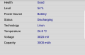
I purchased a variable voltage adapter from Amazon to try to use for powering directly to the battery terminals inside the phone. I can move the slider to change voltage quite precisely according to my multimeter (unfortunately there isn't any display to see on the power supply itself), and since the battery is labled 3.85-4.4V, I've got it tuned to about 4.35V currently. The amperage reading at this setting shows 3.45A. So I can tell the lower voltage the slider is set to, the higher the amperage reading is. This should be plenty of power, and get around the issue most of the articles I found had where they tried to re-purpose USB connectors, which only put off about 500mA.
The first problem I ran into, is the connector on the S7's board for the battery is tiny! I labeled the pins with my terrible paint skills for a multimeter resistance test:

I have a soldering iron, but its a relatively large old thing and I wouldn't trust it for any thing more precise than 2mm. I've only used it in the past for large speaker wiring and such. I'm thinking about ripping the wiring assembly off of the top of this old battery, and seeing if something in it is more accessible to my soldering. But I'm hesitant for two reasons. First, its quite bloated, and I worry about it exploding if I rip off the wrong part... Second, the battery still works for the most part, and its the only way I have of powering up the phone currently to make sure the phone still works.
Here are my resistance readings on the pinouts so far in Ohms:
A to E = 1 (Must be same pin, will refer as AE from here)
D to H = 1 (Must be same pin, will refer as DH from here)
AE to B = Nothing
AE to C = 595
AE to DH = 630
AE to F = 260
AE to G = Nothing
DH to B = Nothing
DH to C = 880
DH to F = 1012
DH to G = Nothing
B C F G = Nothing in any combination
I came across this site in my searches that may answer some questions if it is accurate. But its written in very bad English so I cant understand most of it. Here is the diagram from the site:

The diagram seems to indicate my AE pins are ground, DH are +, C is the battery sensor, and F is something else. They mention BSI is very important, not sure what that is.
So my first few questions are:
1. Does this circuit board diagram appear accurate? Anyone know what I'm dealing with on those red and green highlighted wires?
2. I've read some phones will shut off anyway under these methods unless a resistor is connected to one of the other pins besides + or -, once question 1 is answered, anyone know what resistance is required based on my readings, and what pin to connect?
3. Any advice on how to wire up the connector physically? My first thought just for testing purposes was alligator clips, but I cannot find any small enough for those tiny surfaces, are there any smaller connectors similar to alligator clips that would allow a temporary yet solid connection? Enough that I would be able to turn the phone over and view the screen to make sure it is powering on correctly.
Please let me know if there is any more information I missed that would help determining the solution.
Here are the pictures from the disassembled phone:
I purchased a variable voltage adapter from Amazon to try to use for powering directly to the battery terminals inside the phone. I can move the slider to change voltage quite precisely according to my multimeter (unfortunately there isn't any display to see on the power supply itself), and since the battery is labled 3.85-4.4V, I've got it tuned to about 4.35V currently. The amperage reading at this setting shows 3.45A. So I can tell the lower voltage the slider is set to, the higher the amperage reading is. This should be plenty of power, and get around the issue most of the articles I found had where they tried to re-purpose USB connectors, which only put off about 500mA.
The first problem I ran into, is the connector on the S7's board for the battery is tiny! I labeled the pins with my terrible paint skills for a multimeter resistance test:
I have a soldering iron, but its a relatively large old thing and I wouldn't trust it for any thing more precise than 2mm. I've only used it in the past for large speaker wiring and such. I'm thinking about ripping the wiring assembly off of the top of this old battery, and seeing if something in it is more accessible to my soldering. But I'm hesitant for two reasons. First, its quite bloated, and I worry about it exploding if I rip off the wrong part... Second, the battery still works for the most part, and its the only way I have of powering up the phone currently to make sure the phone still works.
Here are my resistance readings on the pinouts so far in Ohms:
A to E = 1 (Must be same pin, will refer as AE from here)
D to H = 1 (Must be same pin, will refer as DH from here)
AE to B = Nothing
AE to C = 595
AE to DH = 630
AE to F = 260
AE to G = Nothing
DH to B = Nothing
DH to C = 880
DH to F = 1012
DH to G = Nothing
B C F G = Nothing in any combination
I came across this site in my searches that may answer some questions if it is accurate. But its written in very bad English so I cant understand most of it. Here is the diagram from the site:
The diagram seems to indicate my AE pins are ground, DH are +, C is the battery sensor, and F is something else. They mention BSI is very important, not sure what that is.
So my first few questions are:
1. Does this circuit board diagram appear accurate? Anyone know what I'm dealing with on those red and green highlighted wires?
2. I've read some phones will shut off anyway under these methods unless a resistor is connected to one of the other pins besides + or -, once question 1 is answered, anyone know what resistance is required based on my readings, and what pin to connect?
3. Any advice on how to wire up the connector physically? My first thought just for testing purposes was alligator clips, but I cannot find any small enough for those tiny surfaces, are there any smaller connectors similar to alligator clips that would allow a temporary yet solid connection? Enough that I would be able to turn the phone over and view the screen to make sure it is powering on correctly.
Please let me know if there is any more information I missed that would help determining the solution.