I would like to cuss but it is not allowed my long message was wiped out, guess I took to long to type message. Short form.4027 has2 sec.A&B;4528 has 2 secA&B;4066 has a-d a&B used. Eliminate NAND gate connect pin2[4027]to4[4528]. Increase .1 to1μF., 1.5k to 2 meg pot. Optional,replace LM334 with diode[1N914] in series with 2meg pot. I'll add more later when composure returns.
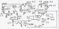
Here is a slightly revised print with a little more labling. A better data sheet on the 4528 would help to identify proper termination of unused pins. I'll try a short explanation: Your shaped pulse at input 3 sets FF,Q goes high starting the charging of C1 at about 13μA. Second pulse resets FF stopping charging,notQ triggers OS A closing SW B charging C2 to C1 V.,trailing edge of pulse triggers OS B, closing SW A, dumping C1. OP Amps present a high Z to caps with a gain of one.
ThanQ bernard
I got ur point. anyways, I'll try to build it today.
One more help regarding the same project.
I need to display the speed of that motor on 7 segment display.
I worked over BCD 2 seven segment decoder. But the pulses from speed sensor must be encoded to BCD.
Again Iam telling that my sensor will generate a pulse / revolution.
I need to count the pulses in one minute and display them on 7 segment...
The total job what im doing can be implemented using a micro controller.
But i dont want to use it. I hav to use total analog and digital ICs.
Help me ....
Here is a slightly revised print with a little more labling. A better data sheet on the 4528 would help to identify proper termination of unused pins. I'll try a short explanation: Your shaped pulse at input 3 sets FF,Q goes high starting the charging of C1 at about 13μA. Second pulse resets FF stopping charging,notQ triggers OS A closing SW B charging C2 to C1 V.,trailing edge of pulse triggers OS B, closing SW A, dumping C1. OP Amps present a high Z to caps with a gain of one.
Hi bernard,
Can i use two normal 555 timers (wired as monostable multi) in place of 4528?
and 4066 is a bilateral switch. Here in this application can i use a transistor(unilateral) in place of the switches?
thank you
Here is a slightly revised print with a little more labling. A better data sheet on the 4528 would help to identify proper termination of unused pins. I'll try a short explanation: Your shaped pulse at input 3 sets FF,Q goes high starting the charging of C1 at about 13μA. Second pulse resets FF stopping charging,notQ triggers OS A closing SW B charging C2 to C1 V.,trailing edge of pulse triggers OS B, closing SW A, dumping C1. OP Amps present a high Z to caps with a gain of one.
Hi bernard,
Im having some doubts in the circuit u attached here.
If thetime gap between the pulses is around 0.1sec,can i use the same time constant components for 4528(a) & 4528(b) for this case?
Im getting the time gap is sround 0.3 seconds.
And can i use LM324 or 741 in place of the opamps shown in ur circuit?
U mentioned something like GAIN=1.
thanQ
I did not know speed was up to 600 rpm. Just keep the sum of all sample and hold pulses less than 100 ms. Same time constant comp. allright. OP's can be of your choice, and usually called "unity gain" ,non inverting buffers.If you are using high Z comparator as load might skip second OP amp. May be able to use 741 single ended, ground - power input as all sig. imputs are above ground. Good luck.
Hi bernard,
Im having some doubts in the circuit u attached here.
If thetime gap between the pulses is around 0.1sec,can i use the same time constant components for 4528(a) & 4528(b) for this case?
Im getting the time gap is sround 0.3 seconds.
And can i use LM324 or 741 in place of the opamps shown in ur circuit?
U mentioned something like GAIN=1.
thanQ
Send me an e-mail address and I'll send you a circuit.
How long is the short pulse? I think that is the one to measure then hold it for the long (.3 to .6 sec. ) pulse. I assume it's a hole in the wheel or something like that.
Send me an e-mail address and I'll send you a circuit.
How long is the short pulse? I think that is the one to measure then hold it for the long (.3 to .6 sec. ) pulse. I assume it's a hole in the wheel or something like that.
Here is a slightly revised print with a little more labling. A better data sheet on the 4528 would help to identify proper termination of unused pins. I'll try a short explanation: Your shaped pulse at input 3 sets FF,Q goes high starting the charging of C1 at about 13μA. Second pulse resets FF stopping charging,notQ triggers OS A closing SW B charging C2 to C1 V.,trailing edge of pulse triggers OS B, closing SW A, dumping C1. OP Amps present a high Z to caps with a gain of one.
Hi bernard,
I want to simulate the circuit first.I treid it practically but iam not getting the output what i want. Instead of the flip flop 4027, i want to use 74HC109 or 74HC107.
In my simulation software 4027 is not there. The available ICs are the two listed above. I tried for the simulation too. But not getting the output.
Can u tell me about the pin connections of any one of the ICs 74HC109 or 74HC107. I dont need the entire circuit. Just tell me where to connect the individual pins. iwant to test the behavior of JK flip flop.
ThanQ
 Facebook
 Google
 GitHub
 Linkedin